Vacuum exhaust apparatus and drive method of vacuum apparatus

a vacuum pump and exhaust technology, applied in mechanical devices, functional valve types, machines/engines, etc., can solve the problems of vapor of vacuum pump oil diffused into the air, the vacuum pump cannot rotate, and the lubrication capacity of the pump deteriorates,

Inactive Publication Date: 2004-09-09
ULVAC INC
View PDF9 Cites 36 Cited by
  • Summary
  • Abstract
  • Description
  • Claims
  • Application Information

AI Technical Summary

Benefits of technology

0035] A further object of the invention is to provide a drive method for a vacuum exhaust

Problems solved by technology

(1) The gasses used in semiconductor manufacturing equipment are strongly reactant in most cases. When such gas is exhausted, it reacts with vacuum pump oil and so produces reaction materials which sometimes makes the vacuum pump impossible to rotate or the pump oil is caused to deteriorate in lubrication capability.
(2) Vapor of the vacuum pump oil diffuses into the vacuum treatment or processing chamber and contaminates it.
(3) Used vacuum pump oil contains arsenic compound and phosphorus compound as toxic material in most cases. Treatment of such harmful industrial waste requires considerable cost and the number of management procedures is also considerable. For the above reasons a recently developed dry vacuum pump (called also a "dry-sealed vacuum pump" according to the international standard ISO/DIS3529/.dagger-dbl.U-1975) which does not use sealing oil, is used instead of the oil-sealed rotary vacuum pump.
However, there is a problem that the required electric power of the dry

Method used


Image

  • Vacuum exhaust apparatus and drive method of vacuum apparatus
  • Vacuum exhaust apparatus and drive method of vacuum apparatus
  • Vacuum exhaust apparatus and drive method of vacuum apparatus

Examples


Embodiment Construction

]

[0068] First, one embodiment of a vacuum exhaust apparatus according to this invention will be described with reference to the drawings of FIG. 1 to FIG. 5, in which a multi-stage dry vacuum pump is used as a main pump.

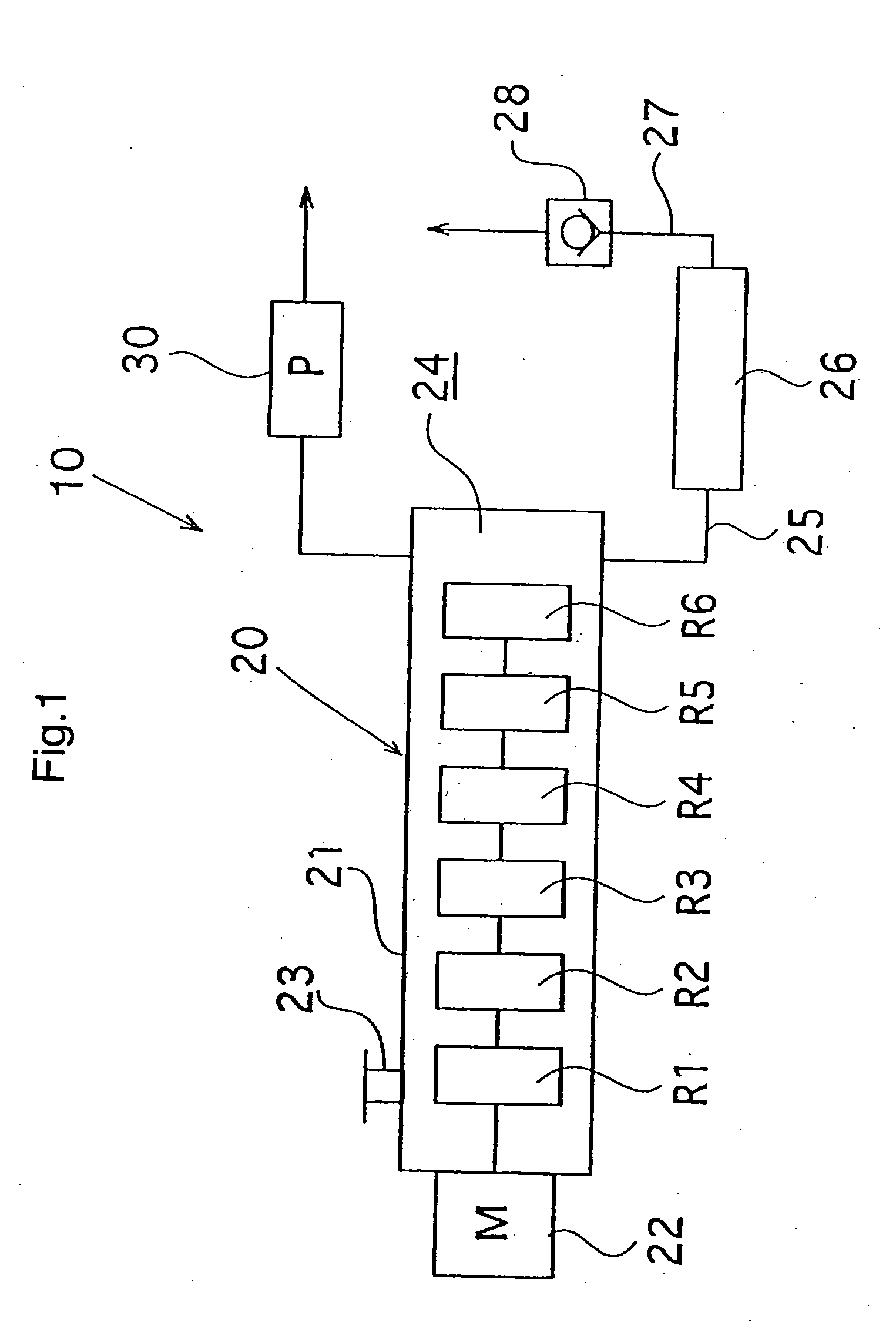
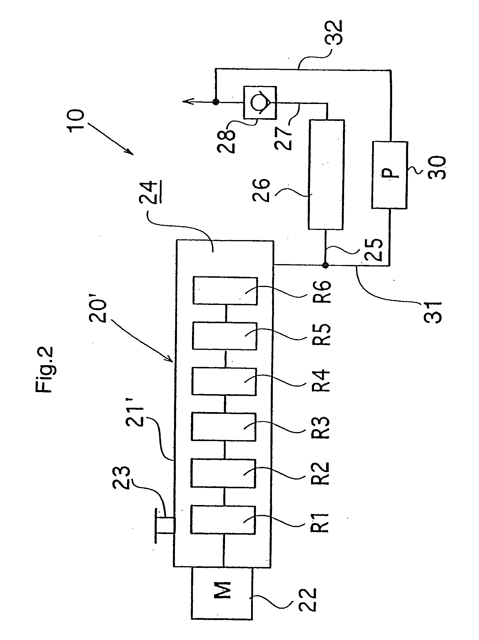
[0069] The multi-stage dry vacuum pump is schematically shown in these figures, In the embodiment of the vacuum exhaust apparatus 10 of FIG. 1, pairs of rotors R.sub.1, R.sub.2, R.sub.3, R.sub.4, R.sub.5 and R.sub.6 are driven by an electric motor 22 and are arranged in a main body 21 of a multi-stage dry vacuum pump 20 (main pump). An inlet port 23 is arranged in an upper wall of the left end of the main body 21. It communicates with a rotor chamber of the rotor R.sub.1. An exhaust pipe 25 provided with a silencer 26 is connected to an outlet portion 24 which is connected to a rotor chamber for rotor R.sub.6 of the last stage. Further, a check valve 28 is connected through pipe 27 to the silencer 26. The check valve 28 permits gas to flow only in the direction towar...


PUM

PropertyMeasurementUnit
Fractionaaaaaaaaaa
Pressureaaaaaaaaaa
Pressureaaaaaaaaaa

Abstract

Pairs of rotors (R1, R2, R3, R4, R5 and R6) driven rotationally by a motor (22) are disposed in the body (21) of a main pump (20) comprising a multistage Roots dry vacuum pump. A suction opening (23) communicating with the rotor chamber of the rotor R1 is provided in the upper wall portion at the left end of the body (21). A delivery section (24) communicating with the delivery side of the rotor chamber of rotor R6 on the final stage is coupled to an exhaust pipe (25) and is provided with a silencer (26) and further coupled to a check valve (28) through a pipe (27). The check valve (28) has its forward direction toward the atmospheric side. The delivery section (24), or a delivery section (24') at the side intermediate stage, is coupled to an auxiliary pump (30) having an exhaust capacity smaller than that of the main pump (20). When the motor (22) is driven, gas exhausted through rotation of the rotors (R1-R6) is carried sequentially to the downstream side from the rotor chambers and a vacuum processing chamber coupled to the suction opening (23) is exhausted. The delivery section (24) on the final stage is exhausted by driving the auxiliary pump (30), and the pressure is reduced. Consequently, the burden of the exhaust action on the rotor (R6) on the final stage or the rotor (R5) on the intermediate stage is lessened, and the power consumption of the motor (22) can be reduced significantly as compared with the prior art.

Description

[TECHNICAL FIELD][0001] This invention relates to a vacuum exhaust apparatus, for example, for semiconductor manufacturing equipment and more particularly to a vacuum exhaust apparatus of the energy conservation type and a driving method for the vacuum exhaust apparatus to reduce consumed electric power.[BACKGROUND OF THE TECHNIQUE][0002] Oil-sealed rotary vacuum pumps were used in most cases for early semiconductor manufacturing equipment. Electric power consumed by the oil-sealed rotary vacuum pump is generally little and it has a construction by which low ultimate pressure can be easily obtained. However, the following points should be noted where the oil-sealed rotary pump is used in semiconductor manufacturing equipment:[0003] (1) The gasses used in semiconductor manufacturing equipment are strongly reactant in most cases. When such gas is exhausted, it reacts with vacuum pump oil and so produces reaction materials which sometimes makes the vacuum pump impossible to rotate or t...

Claims


Application Information

Patent Timeline
IPC IPC(8): F04C23/00
CPCF04C2220/12F04C23/001F16K15/042H01L21/02
Inventor SHIBAYAMA, KOUJIYAMASHITA, YUUICHIYAHAGI, MITSURUTASHIMA, TAKAHIKOAIKAWA, JUNICHITANAKA, TOMONARIKANKE, YUKIOFUKAURA, YUUJI
Owner ULVAC INC
Why Eureka
Try Eureka