Medical charged particle irradiation apparatus

a technology of irradiation apparatus and charged particles, which is applied in the field of medically charged particle irradiation apparatus, can solve the problems of complex mechanism and large size of the entire devi

Inactive Publication Date: 2004-09-23
HITACHI LTD
View PDF9 Cites 57 Cited by
  • Summary
  • Abstract
  • Description
  • Claims
  • Application Information

AI Technical Summary

Benefits of technology

[0015] In contrast, according to the invention, the axis of irradiation of the irradiation field forming means is made eccentric so as to pass a different position from the center of rotation (in other words, the axis of irradiation involves a predetermined angle so as not to intersect the center of rotation), whereby a position of the patient's bed at the time of upward irradiation is not a lowest position as in the above prior art but can rise an amount, which correspond to the above eccentricity, somewhat to a position in either direction laterally of the lowest position. Also, a position of the patient's bed at the time of horizontal irradiation can be correspondingly made a position somewhat lower than the other lateral position unlike the lateral position (the other lateral position in accordance with the above) in the above prior art. That is, the patient's bed 8 when the rotating irradiation body is turned to displace the patient's bed from a position at the time of upward irradiation to a position at the time of horizontal irradiation moves from the position at the time of upward irradiation.fwdarw.gradually descends to a lowest position.fwdarw.gradually ascends to a position at the time of horizontal irradiation. In this manner, since the position of the patient's bed at the time of upward irradiation and the position of the patient's bed at the time of horizontal irradiation are not a lowest position but can be made a position somewhat higher than the lowest position, variation (in other words, difference of height between the lowest position and the position at the time of upward irradiation or the position at the time of horizontal irradiation) of a heightwise position of the patient's bed in displacements, that is, the position at the time of upward irradiation.fwdarw.the lowest position.fwdarw.the position at the time of horizontal irradiation can consequently be suppressed considerably.
[0027] With a construction, in which the axis of rotation of the rotating irradiation body is constituted by the rotating shaft member, it is possible to considerably decrease deformation, such as flexure or the like, due to a weight of large-sized heavy elements such as the transport means, the irradiation field forming means, or the like, as compared with the case where such large-sized heavy elements are supported by a substantially cylindrical-shaped rotary frame provided with no shaft. Thereby, it is possible to prevent that degradation in relative positional accuracy between the target point and the irradiation point, which is attributable to the flexure or the like and to achieve improvement in accuracy of irradiation. Also, the construction provided with a shaft enables a shaft member to support load of all the elements of the rotating irradiation body whereby a diametrical dimension of the rotating irradiation body can be decreased as compared with the case of supporting by means of the substantially cylindrical-shaped rotary frame provided with no shaft.

Problems solved by technology

However, the above prior art involves the following problems.
However, because of the need of providing such moving mechanism as the moving capsule separate from the rotary frame, the entire device becomes large in size (in particular, in the axial direction of the rotary frame) and the mechanism is made complex.

Method used


Image

  • Medical charged particle irradiation apparatus
  • Medical charged particle irradiation apparatus
  • Medical charged particle irradiation apparatus

Examples


Embodiment Construction

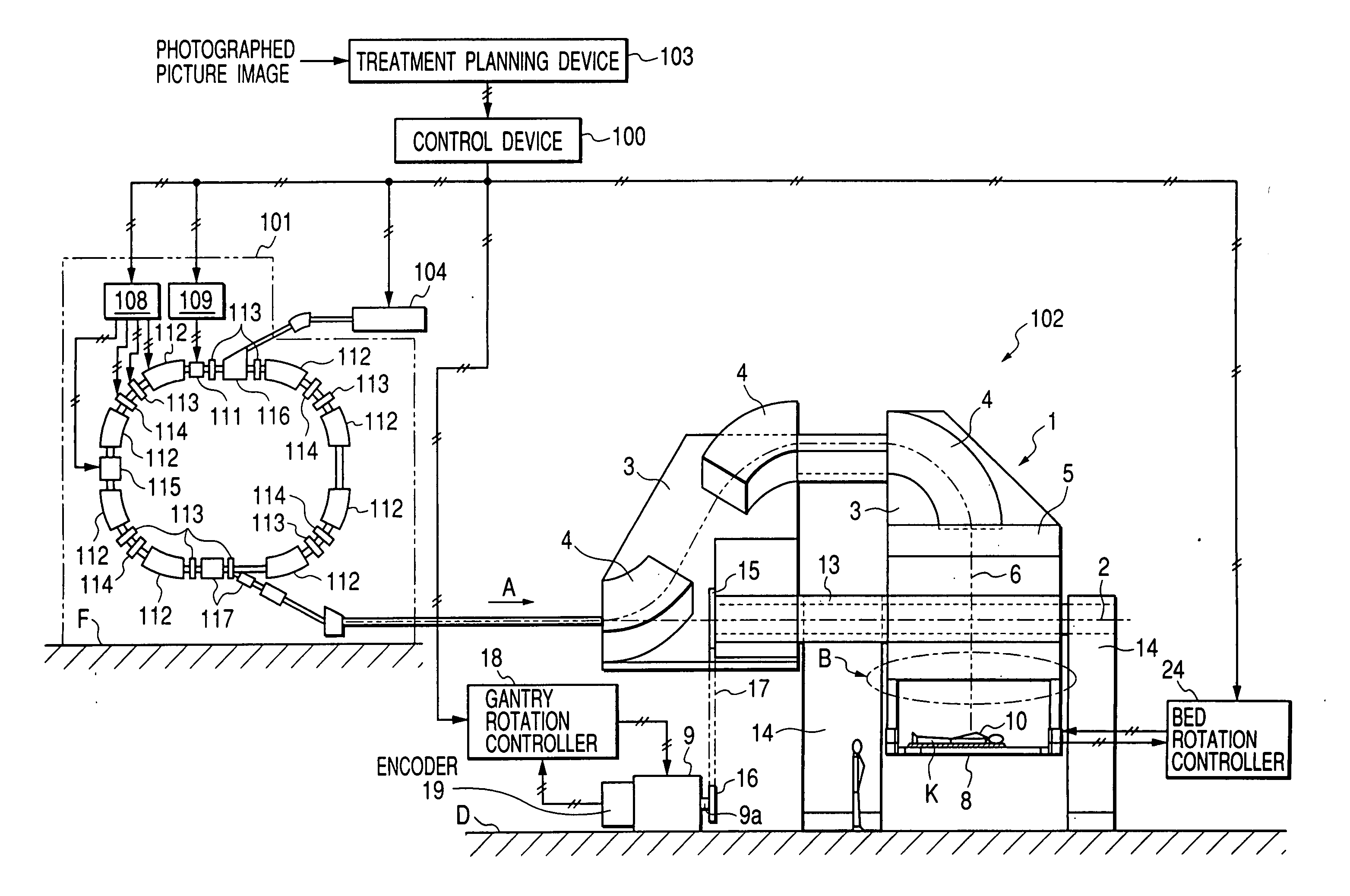
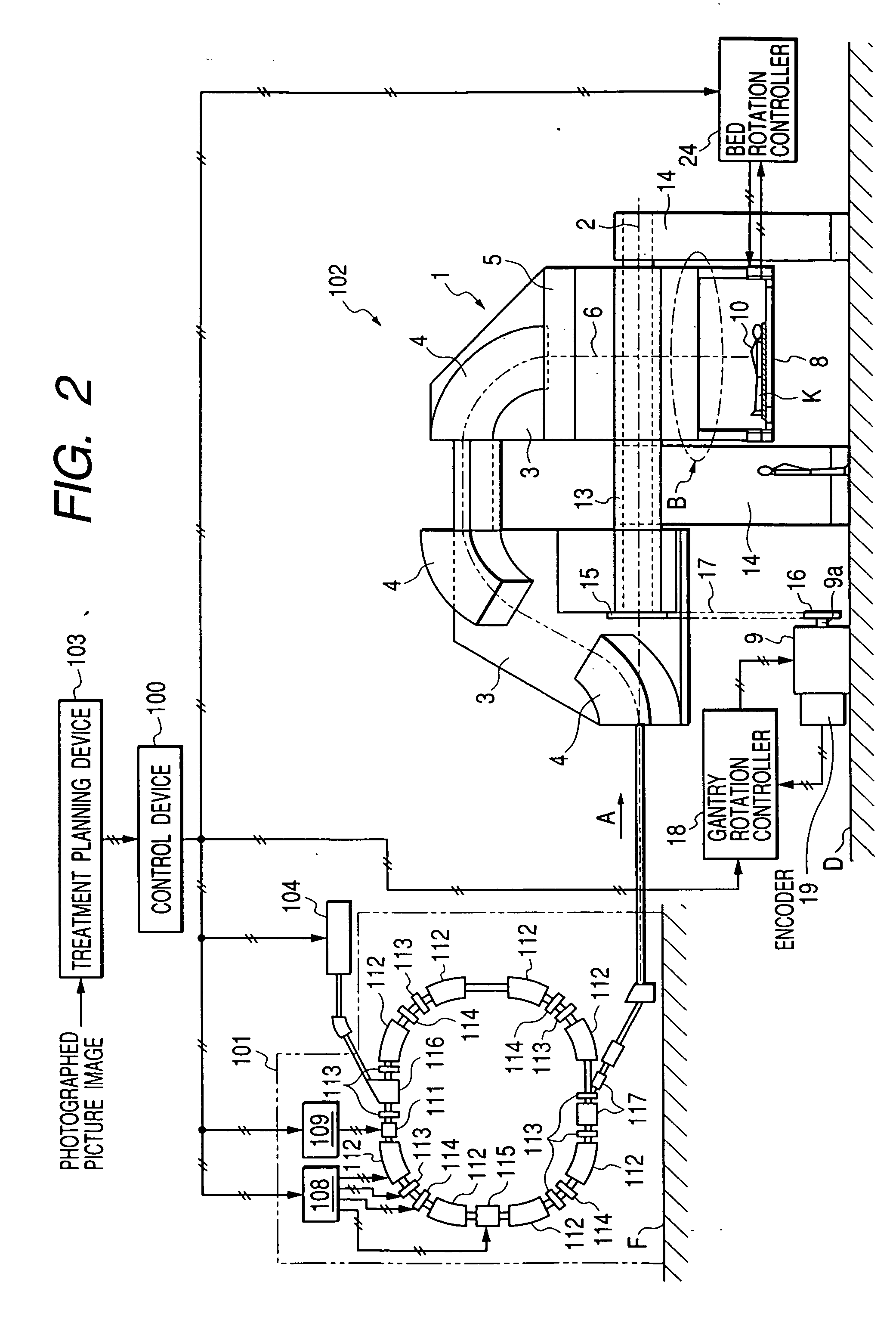
[0093] The medical charged particle irradiation apparatus according to the embodiment, provided in the charged particle irradiation therapeutic system gives the following effect.

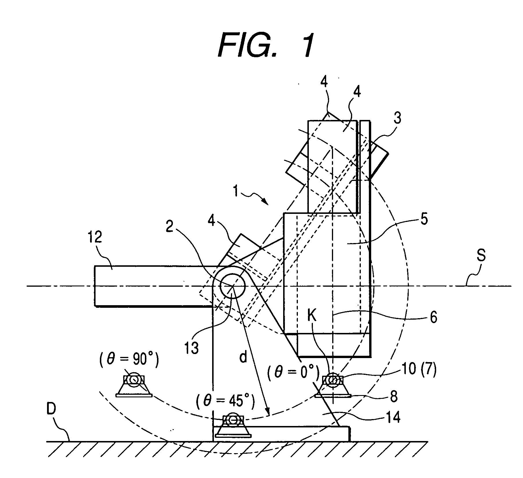
[0094] (5-1) Capability of Upward and Horizontal Irradiation While Suppressing a Patient's Height

[0095] For example, with the above-mentioned construction of the prior art, in which a rotary frame provided with an irradiation chamber capable of turning on its axis is rotated, a position of a patient's bed in a heightwise direction is much varied with a circular motion (vertical motion) of the irradiation chamber caused by rotation of the rotary frame. That is, since a diameter of rotation of an irradiation body provided with a transport means and an irradiation field forming means is around, for example, 5 m, a lift distance from a lowest position of the patient's bed for upward irradiation to a lateral position of the patient's bed for horizontal irradiation in the heightwise direction amounts to about 2.5 ...


PUM


Abstract

A medical charged particle irradiation apparatus capable of irradiation from upward and horizontal directions and performing a preparing / ascertaining work without any separate device such as a moving capsule or the like comprising a patient's bed, on which a patient lies, a transport equipment for injecting and transporting charged particle beams toward the patient's bed, an irradiation field forming device for forming an irradiation field for the beams transported by the transport equipment, and a gantry provided to be rotatable about an axis of rotation, and wherein the irradiation field forming device is eccentrically arranged such that an axis of irradiation passes a position different from the axis of rotation, and the patient's bed is arranged on an opposite side of the transport equipment to a plane, which contains the axis of rotation and is substantially perpendicular to the axis of irradiation.

Description

[0001] 1. Field of the Invention[0002] The invention relates to a medical charged particle irradiation apparatus for using charged particles to treat cancer, lump and so on.[0003] 2. Description of the Related Art[0004] A medical charged particle irradiation apparatus for irradiating charged particles such as proton, carbon ion, or the like on an affected part of a patient to treat cancer, lump and so on injects charged particles, which are generated in an ion source and accelerated by a synchrotron or the like, to guide the same to an irradiation field forming means containing a collimator or the like, and irradiates the charged particles on a patient lying below the irradiation field forming means after an irradiation field conformed to a configuration of the affected part is formed in the irradiation field forming means.[0005] At this time, a patient ordinarily lies on a patient's bed with the face upward, and it is necessary to perform irradiation from an appropriate angular pos...

Claims


Application Information

Patent Timeline
Patent Type & Authority Applications(United States)
IPC IPC(8): A61N5/01G21K5/04A61N5/10G21K5/10
CPCA61N5/10A61N2005/1087A61N5/1081
Inventor YANAGISAWA, MASAKIAKIYAMA, HIROSHIKATO, KOHEI
Owner HITACHI LTD
Why Eureka
Try Eureka