
Thin film magnetic head

Active Publication Date: 2004-09-23
TDK CORPARATION +1
View PDF5 Cites 26 Cited by
  • Summary
  • Abstract
  • Description
  • Claims
  • Application Information

AI Technical Summary

Benefits of technology

[0019] In the thin film magnetic head of the invention, it is more effective when the magnetic pole layer has a stacked-layer structure in which a magnetic layer and a nonmagnetic layer are alternately stacked.

Problems solved by technology

It accompanies an unintended magnetization inverting phenomenon caused by thermal fluctuation, that is, recording demagnetization is becoming a problem.
There is, consequently, a problem that a desired magnetic domain structure is not easily obtained by the material of a single-pole head.
Although the recording medium of the two-layered configuration has an advantage from the viewpoint of efficiency of pulling the magnetic flux for recording, it also has a problem such that when a magnetic flux is leaked from the single-pole head, recording magnetization of the recording medium is disturbed due to the leaked magnetic flux, and information may be unintentionally erased.
If control on the magnetic domain structure of the single-pole head is insufficient, a magnetic flux is unintentionally leaked from the single-pole head due to occurrence of a magnetic domain change (shift of the magnetic domain wall) and it is feared that the recording magnetization of the recording medium is disturbed by the leaked magnetic flux.
However, when considering trends that the saturation magnetic flux density of the material of a head is increasing and the recording track width is being narrowed in association with rapid increase in recording density of recent years, in spite of importance of controlling the magnetic domain structure of a single-pole head in order to prevent unintended magnetic flux leak, the above-described existing techniques have a problem that it is difficult to sufficiently properly control the magnetic domain structure of the single-pole head.

Method used


Image

  • Thin film magnetic head
  • Thin film magnetic head
  • Thin film magnetic head

Examples


first embodiment

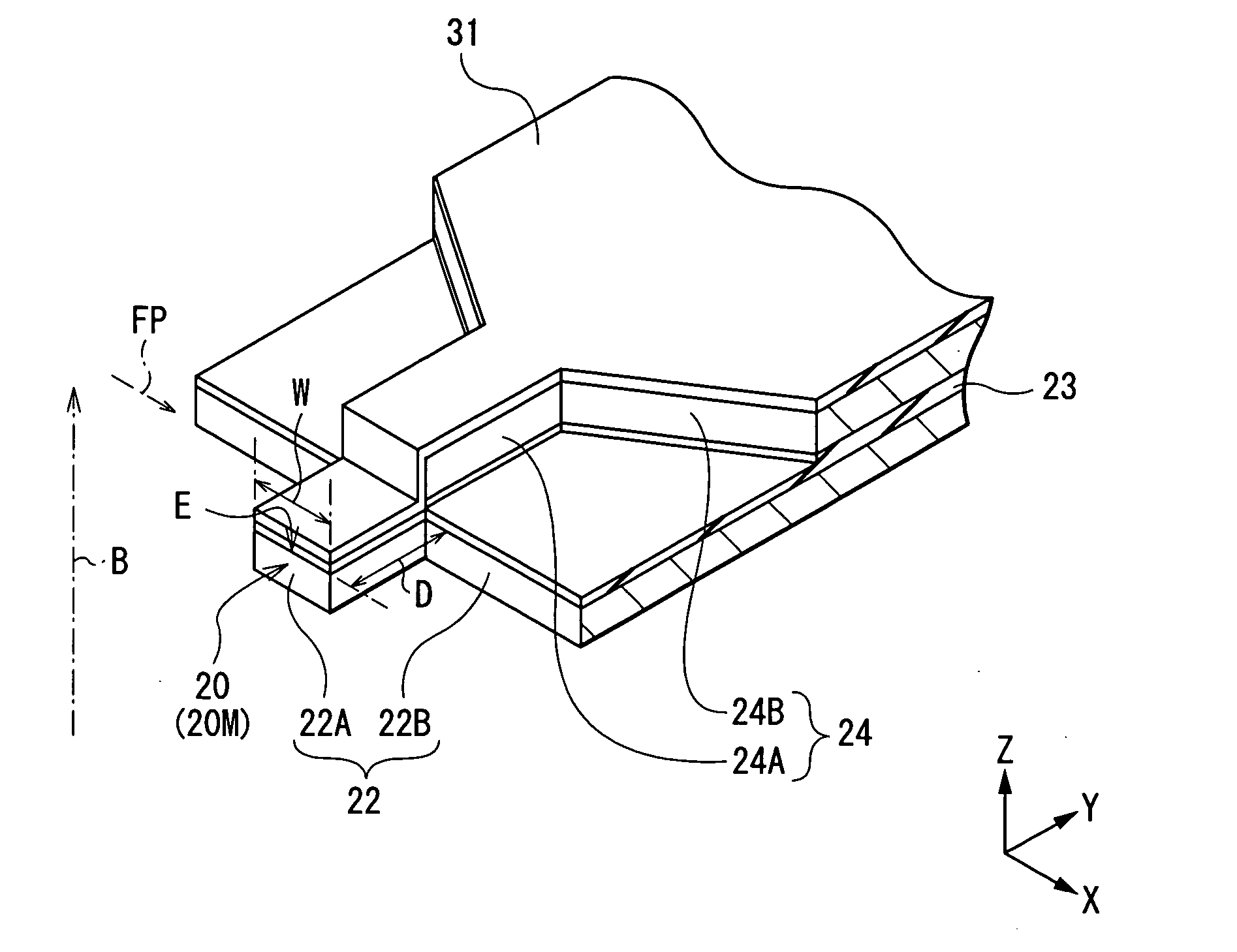
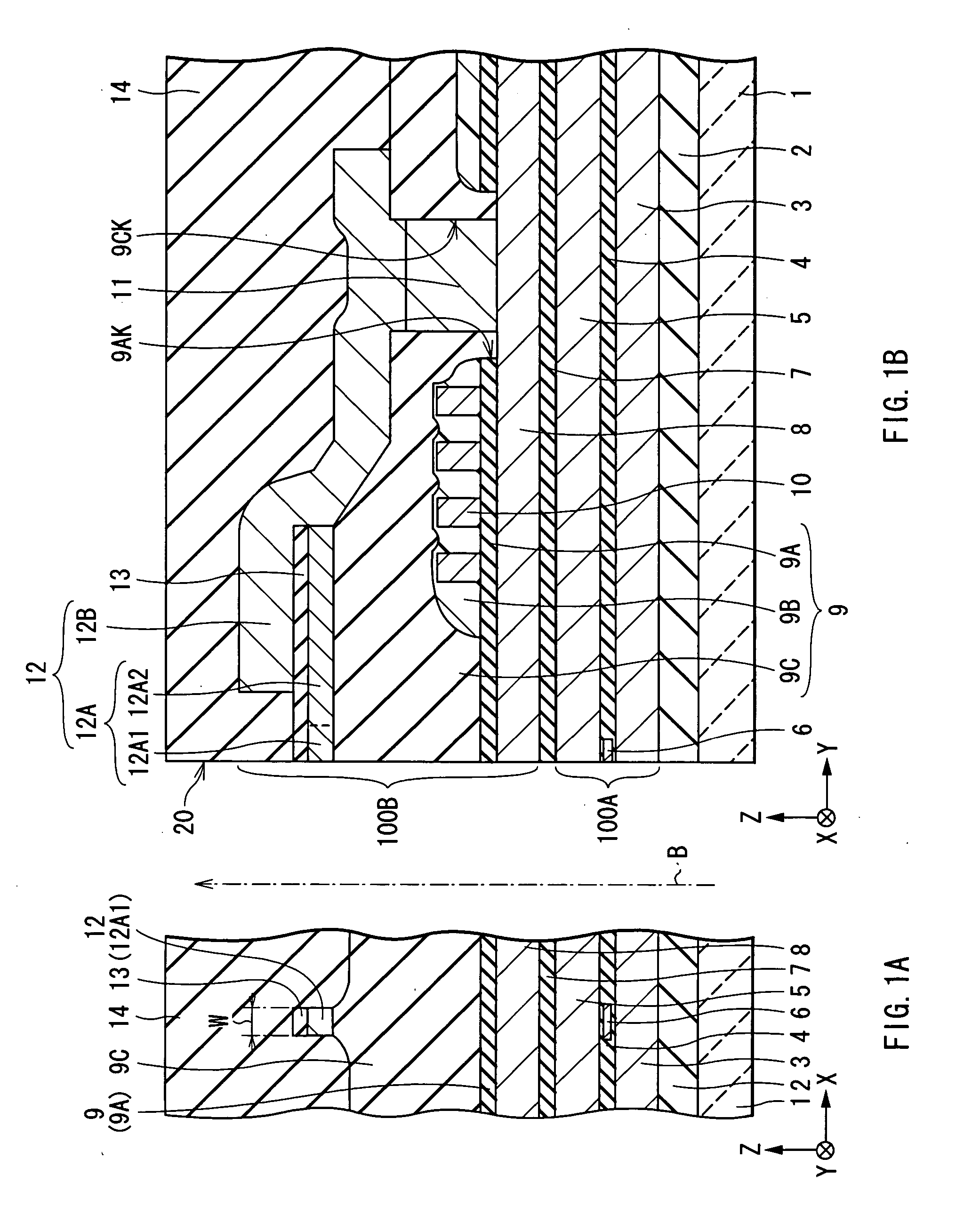
[0034] First, the configuration of a thin film magnetic head according to a first embodiment of the invention will be described with reference to FIGS. 1A and 1B. FIGS. 1A and 1B show sectional configurations of a thin film magnetic head. FIG. 1A shows a section parallel to an air bearing surface and FIG. 1B shows a section perpendicular to the air bearing surface. An upward arrow B shown in FIGS. 1A and 1B indicates the direction in which a recording medium (not shown) travels relative to the thin film magnetic head, that is, the traveling direction of a recording medium (medium traveling direction).

[0035] In the following description, the distance (or direction) in the X-axis direction shown in FIGS. 1A and 1B will be described as "width (or the width direction)", the distance in the Y-axis direction will be described as "length", and the distance in the Z-axis direction will be described as "thickness". The side closer to the air bearing surface in the Y-axis direction will be de...

second embodiment

[0056] A second embodiment of the invention will now be described.

[0057] In a thin film magnetic head according to the second embodiment, to prevent unintended magnetic flux leak, in addition to the "proper formation of the shape of the front end portion 12A1" described in the foregoing first embodiment, the shape of the whole magnetic pole part layer 12A is formed properly, thereby controlling the magnetic domain structure of the magnetic pole part layer 12A.

[0058] FIG. 8 is an enlarged plan view showing the configuration of the magnetic pole part layer 12A. The magnetic pole part layer 12A has, as shown in FIG. 8, a wide shape in which width is larger than length. Specifically, when the length of the whole magnetic pole part layer 12A (that is, the total length of the front and rear end portions 12A1 and 12A2) is set as L1 and the width of the whole magnetic pole part layer 12A (that is, the width of the rear end portion 12A2) is set as L2, the dimensional ratio L1 / L2 of the lengt...

third embodiment

[0063] A third embodiment of the invention will now be described.

[0064] In a thin film magnetic head according to the third embodiment, to prevent unintended magnetic flux leak, in addition to the "proper formation of the shape of the front end portion 12A1" described in the foregoing first embodiment, the magnetic pole part layer 12A is constructed so as to have a stacked structure, thereby controlling the magnetic domain structure of the magnetic pole part layer 12A.

[0065] FIG. 10 is an enlarged cross section showing the configuration of the magnetic pole end surface 20M of the magnetic pole part layer 12A. The magnetic pole part layer 12A has, as shown in FIG. 10, a stacked structure in which a magnetic layer M made of a material having high saturation magnetic flux density such as an iron cobalt alloy and a nonmagnetic layer N made of a nonmagnetic material such as chromium (Cr) are alternately stacked. FIG. 10 shows, as an example, the case of a stacked structure of total five ...


PUM


Abstract

The present invention provides a thin film magnetic head in which a magnetic domain structure of a magnetic pole layer is controlled and fluctuation in recording magnetization caused by leaked magnetic flux generated by unintentional shift of a magnetic domain wall can be prevented. When length of a front end portion which specifying a recording track width of a recording medium, in a magnetic pole part layer is set as D and width of an upper edge positioned on a medium outflow side of a magnetic pole end surface is set as W, a dimensional ratio D / W of the length D to the width W is set so as to lie within the range of 0<D / W<=2.3. Since magnetic domain stability of the magnetic pole part layer is assured on the basis of the proper formation of the shape of the front end portion, leak of magnetic flux from the front end portion immediately after recording is suppressed. Therefore, occurrence of an inconvenience such as unintended erasure of information caused by the leaked magnetic flux is prevented.

Description

[0001] 1. Field of the Invention[0002] The present invention relates to a thin film magnetic head having at least an inductive magnetic transducer for recording and, more particularly, to a thin film magnetic head of a perpendicular recording type for magnetizing a recording medium in the direction orthogonal to the surface of the recording medium at the time of recording.[0003] 2. Description of the Related Art[0004] In recent years, for example, in the field of development of a magnetic recording medium (hereinbelow, simply called "recording medium") such as a hard disk, recording density is increasing and a magnetization transition region in a recording medium is being narrowed. It accompanies an unintended magnetization inverting phenomenon caused by thermal fluctuation, that is, recording demagnetization is becoming a problem. In place of the conventional "longitudinal recording method", the "perpendicular recording method" is being regarded as a promising method which deals wi...

Claims


Application Information

Patent Timeline
IPC IPC(8): G11B5/00G11B5/31G11B5/39G11B5/455
CPCG11B5/3109G11B5/3113G11B5/3116G11B2005/0013G11B5/3967G11B5/455G11B5/3156
Inventor ICHIHARA, SHIGERUODA, AKIHIROROPPONGI, TETSUYAMATONO, NAOTO
Owner TDK CORPARATION
Features
  • Generate Ideas
  • Intellectual Property
  • Life Sciences
  • Materials
  • Tech Scout
  • Unparalleled Data Quality
  • Higher Quality Content
  • 60% Fewer Hallucinations
Learn More