Interlayer for laminated glass and laminated glass

a technology of laminated glass and interlayers, which is applied in the direction of layered products, transportation and packaging, chemical instruments and processes, etc., can solve the problems of moir phenomenon, streak-like diffraction image, diffraction surface, etc., and achieve good cutting workability and good deaeration

Inactive Publication Date: 2004-09-30
SEKISUI CHEM CO LTD
View PDF11 Cites 69 Cited by
  • Summary
  • Abstract
  • Description
  • Claims
  • Application Information

AI Technical Summary

Benefits of technology

0034] In the above state of the art, the present invention has for its object to provide an interlayer for a laminated glass which does not give rise to the moir phenomenon even when the arrangement and pitch of its embossments are orderly, hence providing for good workability in cutting and laminating operations and good deaeration in preliminary contact bonding, thus insuring the production of a laminated glass of high quality with a minimum of rejects for reasons of air bubbles, and a laminated glass containing said interlayer.

Problems solved by technology

However, when such an orderly embossment pattern is generally formed on both sides of the interlayer, the mutual interference of the diffracting surfaces gives rise to a streaks-like diffraction image known generally as the "moir phenomenon".
Furthermore, since the conventional embossment pattern is generally provided in a random fashion by using sand blasted roll, it hardly provides for sufficient deaeration.
The moir phenomenon mentioned above is not only undesirable from appearance points of view but the attention-distracting change of the interference fringes causes an eye strain and motion sickness-like symptoms in the working personnel involved in interlayer cutting and laminating operations, thus leading to the problem of poor workability.
Moreover, even in the case of an interlayer provided with an orderly embossment pattern only on one side, the operation involving the stacking of a plurality of interlayer sheets causes appearance of the moir phenomenon, thus detracting from workability in a similar manner.
It is true that the above method contributes in a considerable measure to attenuation of the above moir phenomenon but since the embossment pattern of finer convex portions is formed to extend not only to surfaces of the larger protruded portions but also surfaces not formed with the larger protruded portions, the pooling of air occurs in concave portions of the embossment between the finer convex portions so that the deaeration in preliminary contact bonding becomes insufficient as a disadvantage.
However, the larger the angle of engraved lines of the roll is, the less easy is the heat transfer to be effected.
Furthermore, in the above technology, unless the temperature at initiation of deaeration in preliminary contact bonding is critically controlled, a premature sealing of the marginal part of the glass-interlayer assembly (e.g. glass / interlayer / glass), i.e. premature marginal sealing, takes place, with the result that the deaeration of the central part of the assembly becomes still more inadequate.
However, there is the problem that in order to achieve a positive marginal seal of the laminate, the temperature for preliminary contact bonding must be considerably raised.
Furthermore, if the linear designs on both sides of the interlayer are made parallel from moldability considerations, the problem will arise that the handleability of the interlayer particularly in terms of self-adhesiveness is adversely affected, i.e. the self-adhesion of the interlayer is increased.
In fact, the above prior art interlayer has been fairly improved in the tendency toward blocking during storage, handling workability, and the efficiency of deaeration in preliminary contact bonding but in the production of a laminated glass having a large surface area or a laminated glass with a large radius of curvature or in carrying out deaeration under the stringent conditions imposed by circumstances calling for increased productivity of laminated glass, for instance, there is the problem that the deaeration and sealing effects are not so satisfactory as desired.
Thus, when deaeration is to be carried out under such stringent conditions, it is difficult, in particular, to establish a uniform seal between the sheet glass and interlayer all over the area and, hence, deaeration and sealing become insufficient, with the result that in the final contact bonding performed under heat and pressure in an autoclave, pressurized air infiltrates through the seal defect to form air bubbles between the glass and the interlayer, thus frustrating to produce a laminated glass of high transparency.
Moreover, when a laminated glass is manufactured using an interlayer such that both the geometry of embosses and the level of depressions are uniform all over as described in the above disclosure, the variation in thickness of the very interlayer film and the pair thickness difference consisting of the difference in thickness or the difference in the radius of curvature of the glass to be laminated cannot be sufficiently absorbed.
In addition, in the case of the prior art interlayer, it is necessary to prepare a large number of embossing rolls having different designs corresponding to various processing needs of users and manufacture many kinds of interlayer films embossed to various three-dimensional patterns compatible with the respective users' processing conditions, this being inefficient from productivity points of view.
Furthermore, when the preliminary contact bonding process involving deaeration by draw deaeration is compared with the process involving deaeration by vacuum deaeration, there is a marked difference in the conditions of deaeration, viz. whereas deaeration is effected at an elevated pressure in the former process, it is effected at a negative pressure in the latter process, so that in establishments having only one kind of equipment, there are cases in which preliminary contact bonding cannot be carried out.
However, when the initial temperature within the rubber bag is set high, the marginal part of the assembly is the first to succumb to the pressure of contact bonding so that the air in the central part is prevented from escaping efficiently but remains entrapped.
However, if the residual amount of air is large, the air will not be completely dissolved in the final contact bonding stage so that air bubbles appear in the product laminated glass.
On the other hand, if the ultimate temperature is set too low, an incomplete seal occurs locally in the marginal region and as the pressurized air finds its way into such localities in the final contact bonding stage, air bubbles are produced in the product laminate.
This method, however, has the disadvantage that while the initial temperature within the rubber bag can be set high, the ultimate temperature must also be set high and if the ultimate temperature is set low, the infiltration of air will occur in the final contact bonding stage to cause air bubbles.
In the method referred to above, however, the formation of air bubbles cannot be avoided unless the heating is performed from an initial temperature of 35.degree. C. to an ultimate temperature of 95.degree. C. so that even if the depth (height), width, and pitch of troughs or ridges are optimized, the embossments must be collapsed to a certain volume.

Method used


Image

  • Interlayer for laminated glass and laminated glass
  • Interlayer for laminated glass and laminated glass
  • Interlayer for laminated glass and laminated glass

Examples


example 2

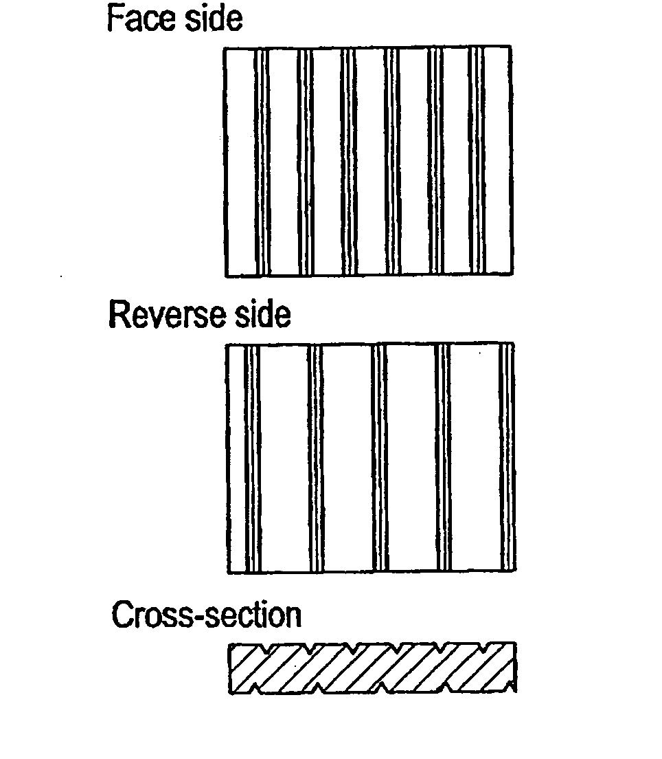
[0184] Except that the pitch of the embossment of one engraving mill (mother mill) was changed to 300 .mu.m and the pitch of the embossment of the other engraving mill (mother mill) was changed to 375 .mu.m, the procedure of Example 1 was repeated to manufacture an interlayer for a laminated glass having an orderly array of linear embossments on both sides and varying in the pitch of embossments from one side to the other side.

example 3

[0185] Except that the pitch of the embossments of one engraving mill (mother mill) was changed to 300 .mu.m and the pitch of the embossments of the other engraving mill (mother mill) was changed to 430 .mu.m, the procedure of Example 1 was repeated to manufacture an interlayer for a laminated glass having an orderly array of linear embossments on both sides and varying in the pitch of embossments from one side to the other side.

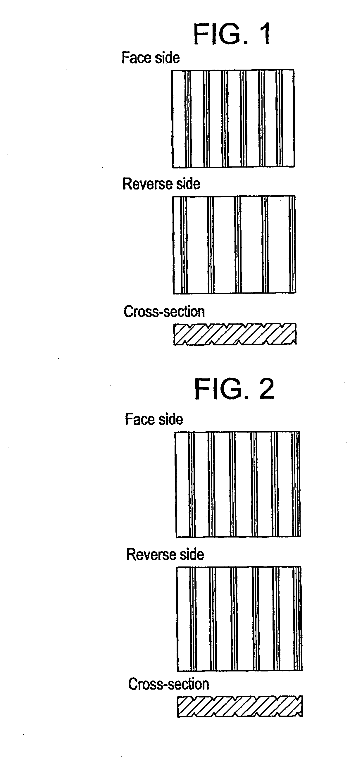
[0186] The face side, reverse side, and cross-section views of the embossment designs (concave and convex patterns) of the interlayers for laminated glass as obtained in Examples 1 to 3 are schematically illustrated in FIG. 1.

example 4

[0189] To 100 parts by weight of polyvinyl butyral resin (average degree of polymerization 1700, residual acetyl group 1 mol %, butyralization degree 65 mol %) was added 40 parts by weight of the plasticizer triethylene glycol-di-2-ethylbutyrate (3 GH) and, using an extruder, the resulting mixture was melt-kneaded and extruded in a sheet form from the extrusion die to give a 0.76 mm-thick polyvinyl butyral resin sheet (PVB sheet).

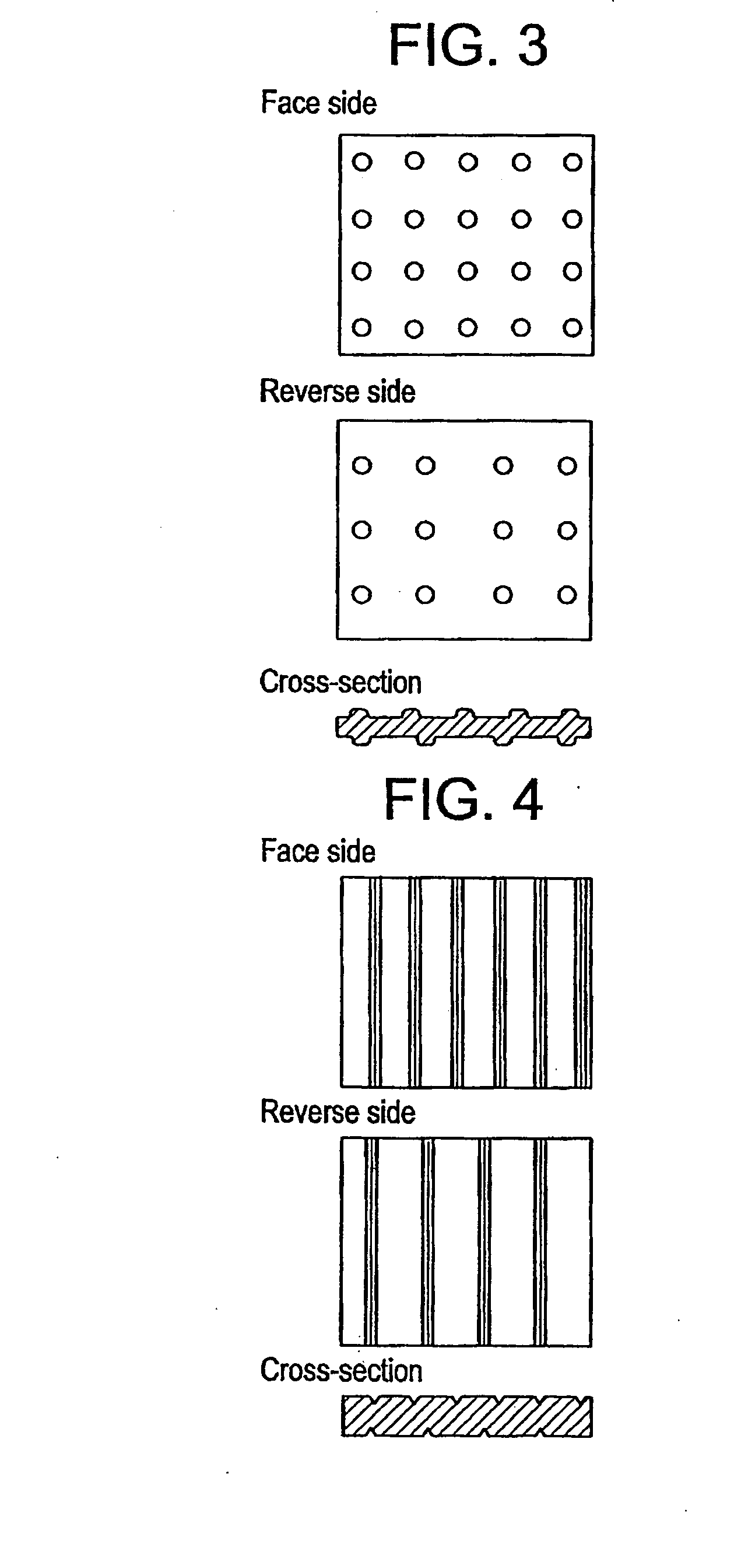
[0190] An engraving mill (mother mill) having a hemispherical embossment design was forced against the surface of one of a pair of metal embossing rolls and this metal roll and the engraving mill were driven in association to transfer the embossment design of the engraving mill to the metal roll. Then, the engraving mill was shifted in the axial direction of the metal roll in steps of the unit embossment design to transfer the embossment design of the engraving mill to the metal roll in the same manner as above to construct an embossing roll having an order...


PUM

PropertyMeasurementUnit
surface roughnessaaaaaaaaaa
angleaaaaaaaaaa

Abstract

The present invention provides an interlayer for a laminated glass which does not give rise to the moiré phenomenon even when the arrangement and pitch of its embossments are orderly, hence providing for good workability in cutting and laminating operations and good deaeration in preliminary contact bonding, thus insuring the production of a laminated glass of high quality with a minimum of rejects for reasons of air bubbles, and a laminated glass containing said interlayer. The invention also provides an interlayer for a laminated glass which provides for good deaeration without a risk for premature marginal sealing even if the temperature at initiation of deaeration at preliminary contact bonding is not critically controlled and which does not require raising of temperature for achieving a marginal seal of the glass-interlayer assembly, and a laminated glass containing said interlayer.

Description

[0001] This is a divisional of application Ser. No. 10 / 019,656 filed Feb. 12, 2002; which is a .sctn.371 National Stage Application of PCT Application No. PCT / JP00 / 04383 filed Jul. 3, 2000; the disclosure of which is incorporated herein by reference.[0002] The present invention relates to an interlayer for a laminated glass providing for improved deaeration and a laminated glass comprising the same.[0003] The laminated glass manufactured by interposing an interlayer comprising a sheet made of a thermoplastic resin such as plasticized polyvinyl butyral between glass sheets and bonding them together into an integral unit is in broad use for glazing the windows of automobiles, aircraft, and buildings.[0004] When such a laminated glass is subjected to an external impact, the glass may break up but the interlayer sandwiched between the component glass sheets will not readily be destroyed and even after breakage, the glass remains glued to the interlayer so that its fragments will not be ...

Claims


Application Information

Patent Timeline
Patent Type & Authority Applications(United States)
IPC IPC(8): B32B3/00B32B17/10C03C27/12
CPCB29C59/022B29C59/04B29C2059/023B29K2029/00B32B17/10577Y10T428/24612Y10T428/24628Y10T428/2457Y10T428/24355Y10T428/24479B32B17/10761B32B17/10587Y10T428/3163Y10T428/31518B29K2029/14C03C27/10B32B17/06B32B17/10
Inventor NAKAJIMA, MINORUSANNOMIYA, ISEI
Owner SEKISUI CHEM CO LTD
Why Eureka
Try Eureka