Method and apparatus for optically detecting and locating a fire in an enclosed space

a fire and enclosed space technology, applied in the field of methods and apparatus for optically detecting and locating fires in enclosed spaces, can solve the problems of insufficient development of automatic interpretation algorithms for determining whether a fire is detected, system not yet in actual practical use, and insufficient reliability of optically monitored spa

Active Publication Date: 2004-10-28
AIRBUS OPERATIONS GMBH
View PDF17 Cites 12 Cited by
  • Summary
  • Abstract
  • Description
  • Claims
  • Application Information

AI Technical Summary

Problems solved by technology

Such systems, however, are not yet in actual practical use due to shortcomings and problems in the development thereof.
Particularly, algorithms for automatically interpreting optically obtained information for determining whether a fire does or does not exist in the optically monitored space are not yet adequately developed to the required level of reliability.
Thus, it is estimated that optical fire verification systems will not be in actual use in aircraft freight compartments for the next two to six years, with respect to an automatic fire detection and verification by such a system.
It is also essentially not possible with such conventional systems to precisely determine the location of a fire in the freight compartment.
While the location of the fire can be visually estimated, the precision of such locating depends on the number of cameras being used in the system, and is thus very cost intensive.
A further disadvantage of such known systems using CCD cameras is that only temperatures above about 300.degree. C. can be visually detected and measured due to the wavelength dependence.
While such a system provides for the active combat and extinguishing of a fire in connection with video monitoring of an enclosed space, such a system is not suitable for detecting and locating an outbreak of a fire in the first place.

Method used


Image

  • Method and apparatus for optically detecting and locating a fire in an enclosed space
  • Method and apparatus for optically detecting and locating a fire in an enclosed space

Examples


Embodiment Construction

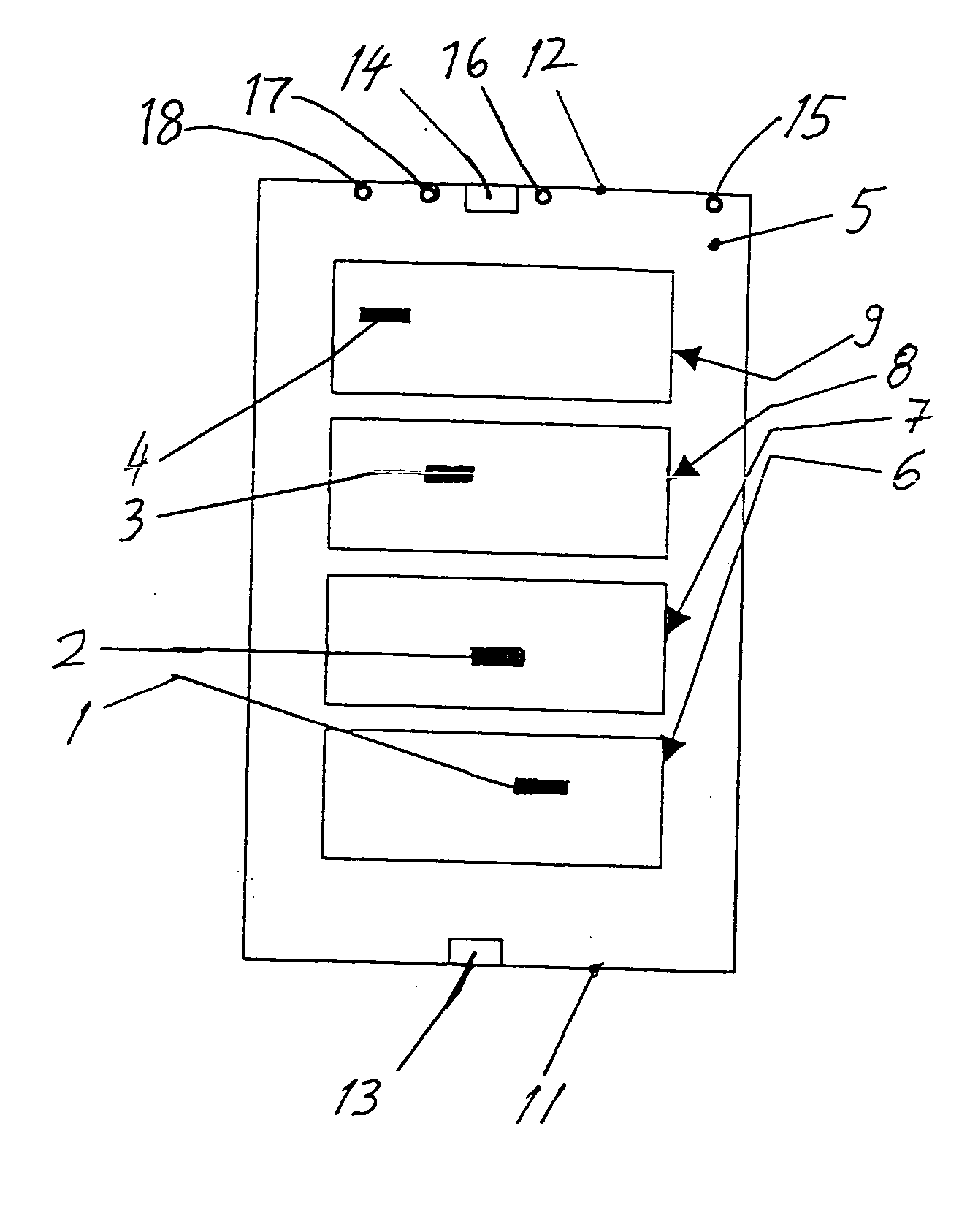
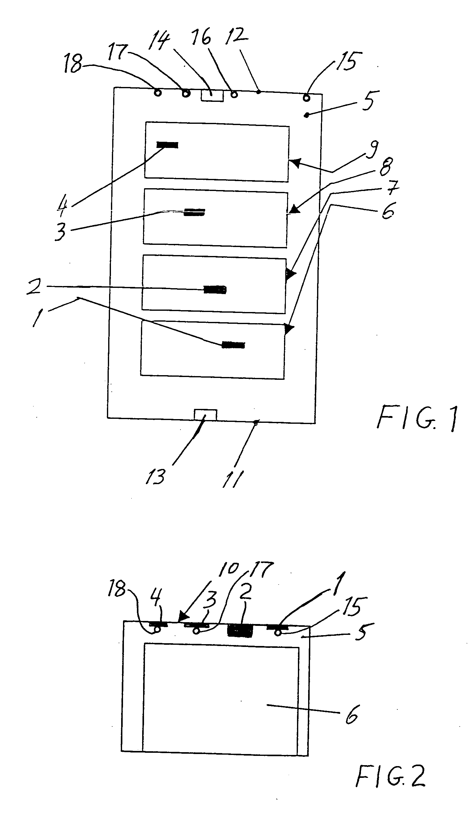
[0018] FIG. 1 schematically represents a top view onto or into a freight compartment 5 of an aircraft representing an enclosed space that is to be optically monitored for fire detection according to the invention. Four cargo load units such as cargo or freight pallets or especially containers 6, 7, 8 and 9 are arranged at respective stowage positions within the freight compartment 5. A plurality of thermally reactive elements, particularly being intumescent material strips 1, 2, 3 and 4, are arranged in a predefined pattern on the ceiling 10 of the freight compartment 5. Namely, one of these intumescent material strips 1, 2, 3 and 4 is respectively arranged above each one of the containers 6, 7, 8 and 9 on the ceiling 10.

[0019] In addition to being spaced from one another respectively above the containers in the longitudinal direction of the aircraft, the intumescent material strips 1, 2, 3 and 4 are transversely or laterally offset from one another or staggered, as will be describe...


PUM

PropertyMeasurementUnit
trigger temperatureaaaaaaaaaa
temperaturesaaaaaaaaaa

Abstract

Thermally reactive elements of an intumescent material that expands when heated above a trigger temperature are arranged in an enclosed space, e.g a freight compartment of an aircraft. An optical sensor in the enclosed space has a field of view encompassing the elements. An evolving fire heats one of the elements above the trigger temperature so the intumescent material expands. This expansion of the element is sensed by the optical sensor, for an early detection of the fire at temperatures substantially below 300° C. With the elements arranged in a predefined pattern, the location of the fire can be determined based on the element(s) that has/have expanded. The intumescent material may be an adhesive tape adhered onto the ceiling of the freight compartment. Light sources or optical targets arranged along lines of sight behind the elements enhance the unambiguous recognition of the thermally expanded condition of a respective element.

Description

PRIORITY CLAIM[0001] This application is based on and claims the priority under 35 U.S.C. .sctn.119 of German Patent Application 103 18 976.9, filed on Apr. 26, 2003, the entire disclosure of which is incorporated herein by reference.[0002] The invention relates to a method as well as an apparatus for optically detecting a fire, e.g. using a video or IR camera or sensor, in an enclosed space, for example in a freight or cargo compartment of an aircraft.BACKGROUND INFORMATION[0003] Fire verification systems are being developed for use in freight compartments of aircraft. Such systems, however, are not yet in actual practical use due to shortcomings and problems in the development thereof. Particularly, algorithms for automatically interpreting optically obtained information for determining whether a fire does or does not exist in the optically monitored space are not yet adequately developed to the required level of reliability. Furthermore, any such algorithms must still be tested f...

Claims


Application Information

Patent Timeline
Patent Type & Authority Applications(United States)
IPC IPC(8): A62C2/06A62C3/08A62C37/36B64D25/00G08B17/00
CPCA62C2/065A62C3/08A62C37/36B64D25/00G08B17/125
Inventor BOBENHAUSEN, AXEL
Owner AIRBUS OPERATIONS GMBH
Why Eureka
Try Eureka