

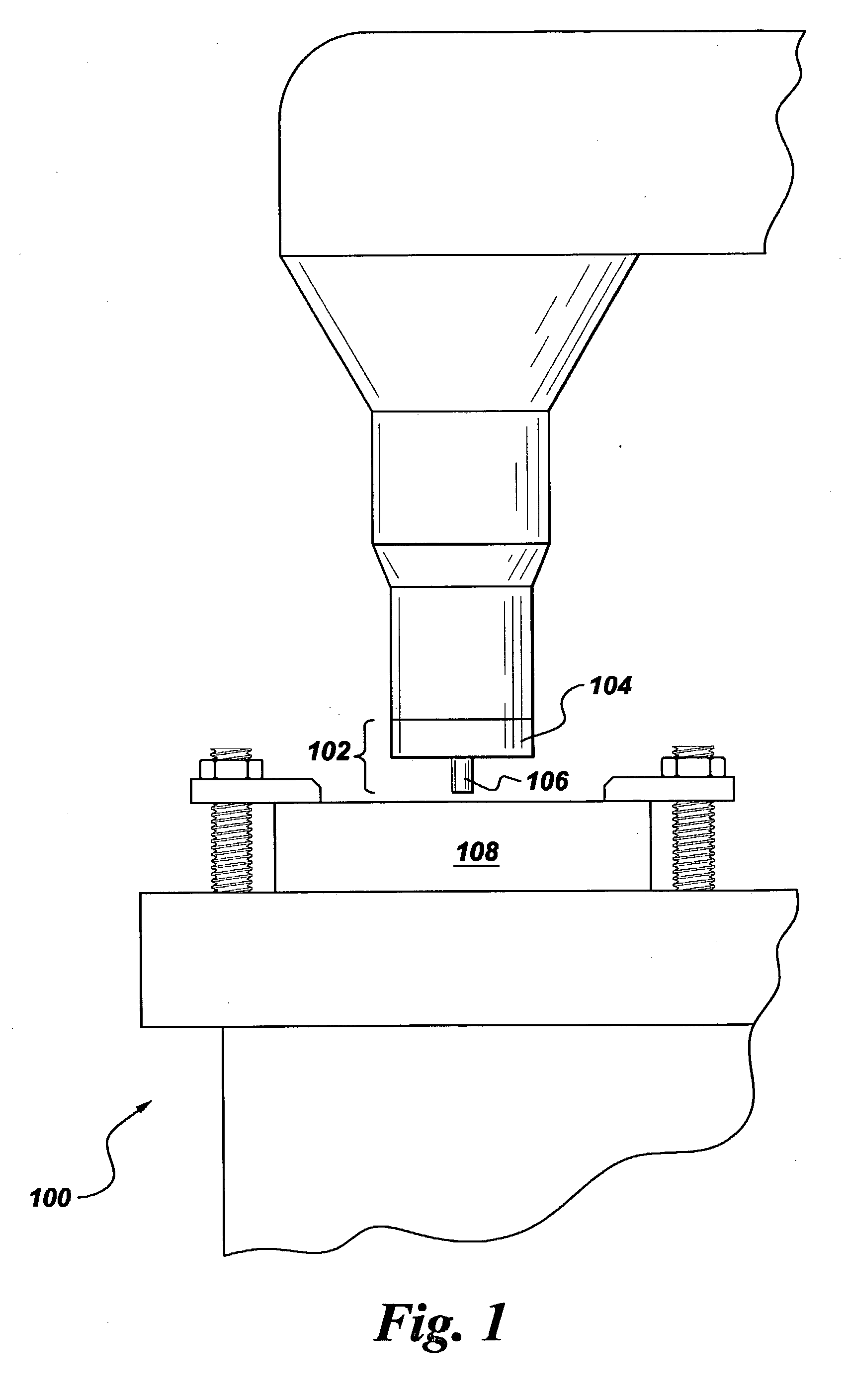
Apparatus and method for friction stir welding of high strength materials, and articles made therefrom
a high-strength material and friction stir technology, applied in the direction of soldering apparatus, manufacturing tools, auxillary welding devices, etc., can solve the problems of inability to use alloys in machine design, material often comes at the expense of other properties, and localized degradation of the properties of many such materials, so as to reduce the cross-sectional area of feedstock.
- Summary
- Abstract
- Description
- Claims
- Application Information
AI Technical Summary
Benefits of technology
Problems solved by technology
Method used
Image

Examples
examples
[0038] The following examples are presented to further illustrate certain embodiments of the present invention, and should not be construed as limiting the invention in any way.
[0039] Example 1: A friction stir welding tool made of H-13 tool steel was used in an attempt to weld via FSW a workpiece made of the nickel-based superalloy Alloy 718. Tool steel is a material commonly used to fabricate tools for FSW of aluminum workpieces. However, when applied to the Alloy 718 workpiece in this example, the tool made of tool steel was unable to bear the stress needed to plunge the tool into the workpiece, and the tool fractured during the initial stages of processing.
example 2
[0040] A friction stir welding tool made of a sintered tungsten alloy containing about 25 weight percent rhenium was used in an attempt to weld via FSW a workpiece made of Alloy 718. Unlike the conventional tool made of tool steel in Example 1, the tungsten-rhenium tool remained intact throughout the welding process, and successfully welded the workpiece. Metallographic examination of the weld in cross section detected a number of small debris particulates entrapped in the weld from the wear of the tool during the FSW process. Although a strong bond was formed, the number and size of entrapped particulates would render the weld unacceptable in certain critical applications involving high stress and elevated temperatures.
example 3
[0041] A friction stir welding tool made of a cast and extruded tungsten alloy containing about 4weight percent rhenium and about 0.5 weight percent hafnium carbide was used in an attempt to weld one workpiece made of titanium alloy Ti17to another workpiece made of Ti6-4. This tool remained intact throughout the welding process and successfully welded the workpiece, as did the tool in Example 2. Metallographic examination of the weld in cross section did not detect any of the debris particulates observed in Example 2.
PUM
| Property | Measurement | Unit |
|---|---|---|
| Fraction | aaaaa | aaaaa |
| Fraction | aaaaa | aaaaa |
| Fraction | aaaaa | aaaaa |
Abstract
Description
Claims
Application Information