Production method for a sensor head for optical current sensors

a production method and sensor technology, applied in the direction of magneto-optic devices, instruments, angle measurements, etc., can solve the problems of inaccuracy of measurement, the relationship between the current to be measured and the measurement signal no longer being linear, and complicating the evaluation of measurements

Inactive Publication Date: 2004-12-09
ABB RES LTD
View PDF1 Cites 12 Cited by
  • Summary
  • Abstract
  • Description
  • Claims
  • Application Information

AI Technical Summary

Problems solved by technology

One problematic feature of this type of compensation from the temperature dependency of the Verdet constant V is that it results in the relationship between the current to be measured and the measurement signal no longer being linear, with the measurement signal generally being proportional to .DELTA..PHI..sub.S or .D

Method used


Image

  • Production method for a sensor head for optical current sensors
  • Production method for a sensor head for optical current sensors
  • Production method for a sensor head for optical current sensors

Examples


Embodiment Construction

[0014] The object of the invention is to provide an improved current or magnetic field sensor of the type mentioned initially, and a corresponding measurement method. This sensor is intended to overcome the disadvantages mentioned above. In particular, the sensor is intended to have better measurement accuracy and / or to simplify the evaluation of the measurement and to make it unnecessary to use complex signal processing.

[0015] This object is achieved by a method for production of a sensor head for an optical current or magnetic field sensor having the features of patent claim 1, and by a method for production of an optical current or magnetic field sensor as claimed in patent claim 11, and an optical current or magnetic field sensor as claimed in patent claim 12, and a method for measurement of an electrical current or a magnetic field having the features of patent claim 13.

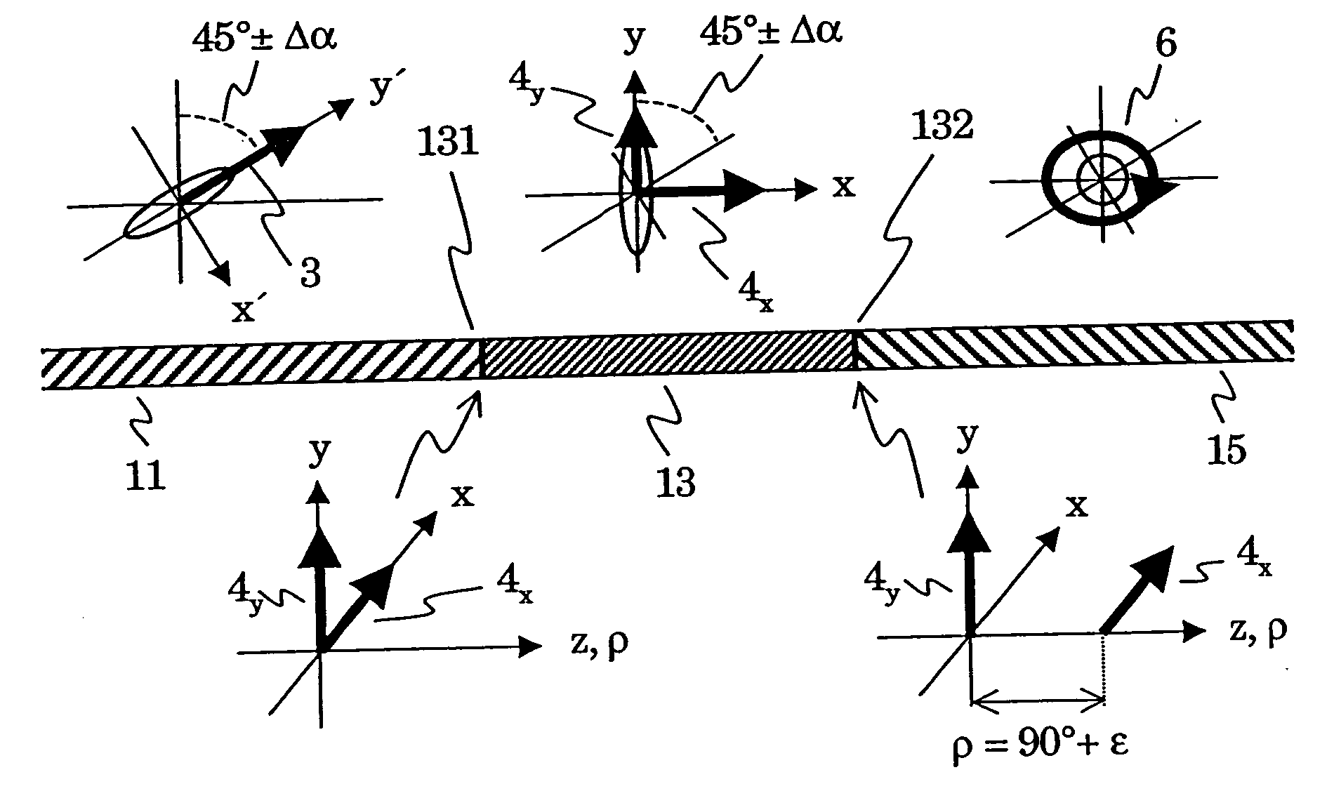
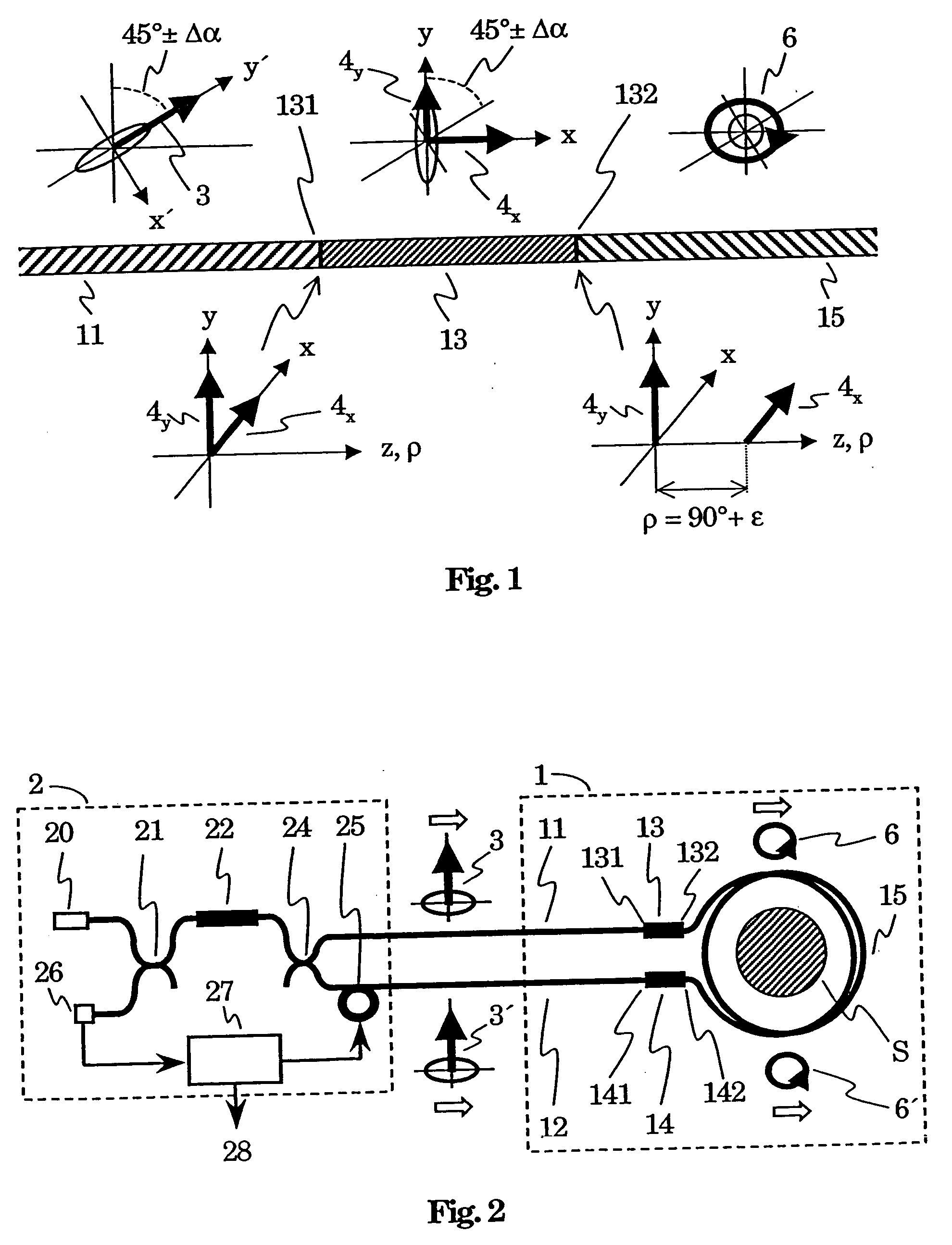
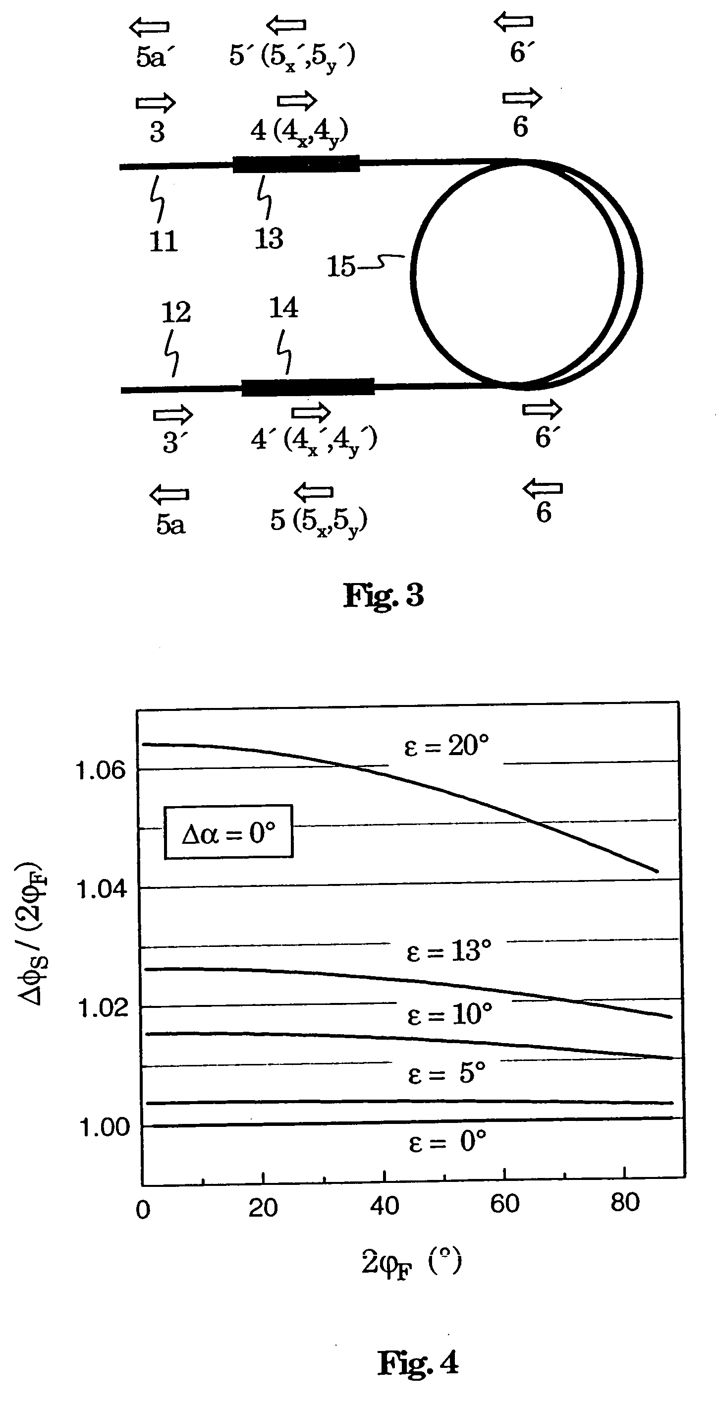
[0016] The optical current or magnetic field sensor has a sensor head with a sensor element and two phase del...


PUM


Abstract

An optical current or magnetic field sensor has a sensor head which has a first phase delay element (13), a second phase delay element and a sensor fiber (15) The two phase delay elements (13) are optically connected to opposite ends of the sensor element (15), and the phase delay angle rho on at least one of the phase delay elements (13) deviates by an angle epsilon, with epsilon<>0°, from 90°. Linearly polarized light waves (3) are injected into the first phase delay element (13), with a polarization axis (y') of these linearly polarized light waves (3) including an angle which deviates from 45° by an angle Deltaalpha, with Deltaalpha<>0°, with a principal axis (y) of the first phase delay element (13). The angle Deltaalpha is selected as a function of at least the angle epsilon. This choice of the angle Deltaalpha makes it possible to compensate for non-linearities between a direct measurement signal and an electrical current or magnetic field to be measured which occur because of the angle epsilon<>0°.

Description

[0001] The present invention relates to the field of optical current and magnetic field sensor systems. It relates in particular to[0002] a method for production of a sensor head as claimed in the precharacterizing clause of patent claim 1,[0003] an optical current or magnetic field sensor as claimed in the precharacterizing clause of patent claim 12, and to a method for its production, and[0004] to a method for measurement of an electrical current or magnetic field as claimed in the precharacterizing clause of patent claim 13.PRIOR ART[0005] An optical current sensor such as this is known from EP 0 856 737 A1. This has a sensor fiber which is wound in the form of a coil, is magneto-optically active and surrounds an electrical conductor. At least at one end, the sensor fiber is connected via a phase delay element to a further optical fiber, a so-called supply fiber or return fiber, via which light can be injected into or output from the sensor fiber. The supply and return fibers pre...

Claims


Application Information

Patent Timeline
IPC IPC(8): G01R15/24G01R33/032
CPCG01R3/00G01R15/246G01R33/0322
Inventor BOHNERT, KLAUSNEHRING, JURGEN
Owner ABB RES LTD
Why Eureka
Try Eureka