Alkaline dry cell

a dry cell and alkaline technology, applied in dry cells, cell components, electrical equipment, etc., can solve the problems of internal electrolyte solution leakage from the sealing portion, difficult machining process, external can tend to be deformed, etc., to increase the actual increase the inner capacity of the battery, and increase the discharging capacity

Inactive Publication Date: 2004-12-16
HITACHT MAXELL LTD
View PDF9 Cites 7 Cited by
  • Summary
  • Abstract
  • Description
  • Claims
  • Application Information

AI Technical Summary

Benefits of technology

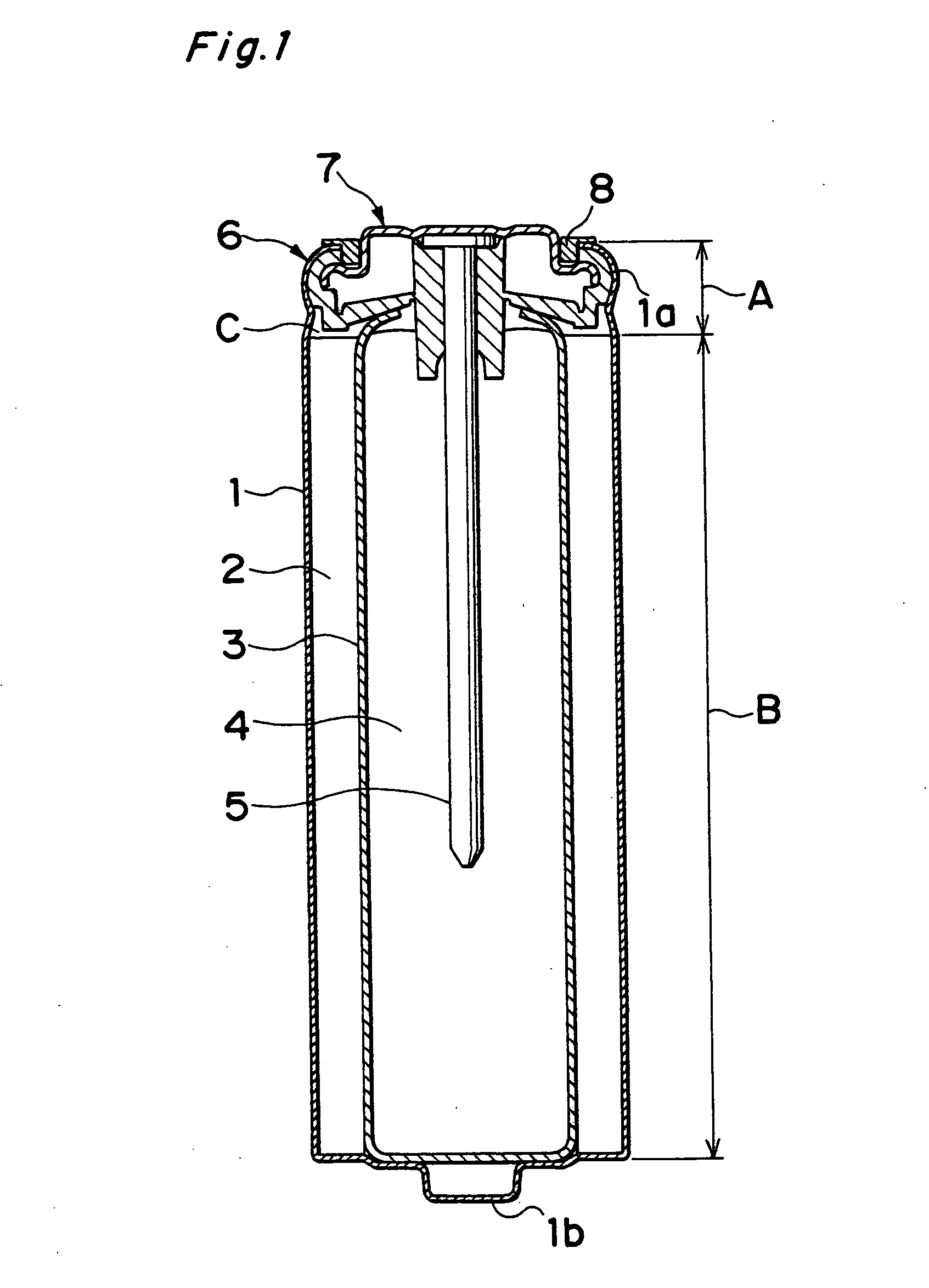
0064] In accordance with the invention relating to claim 1, the can thickness of the sealing edge portion of the external can is set to not less than 1.4 times the can thickness of the trunk portion; therefore, even when the thickness of the trunk portion of the external can is set to not more than 0.18 mm, it becomes possible to positively prevent the solution leaking phenomenon due to temperature changes. Therefore, even in the case of an alkaline dry cell in which the trunk portion of the external can is made thinner to increase the battery inner capacity and consequently to increase the discharging capacity, it is possible to ensure a desired leaking resistant property.
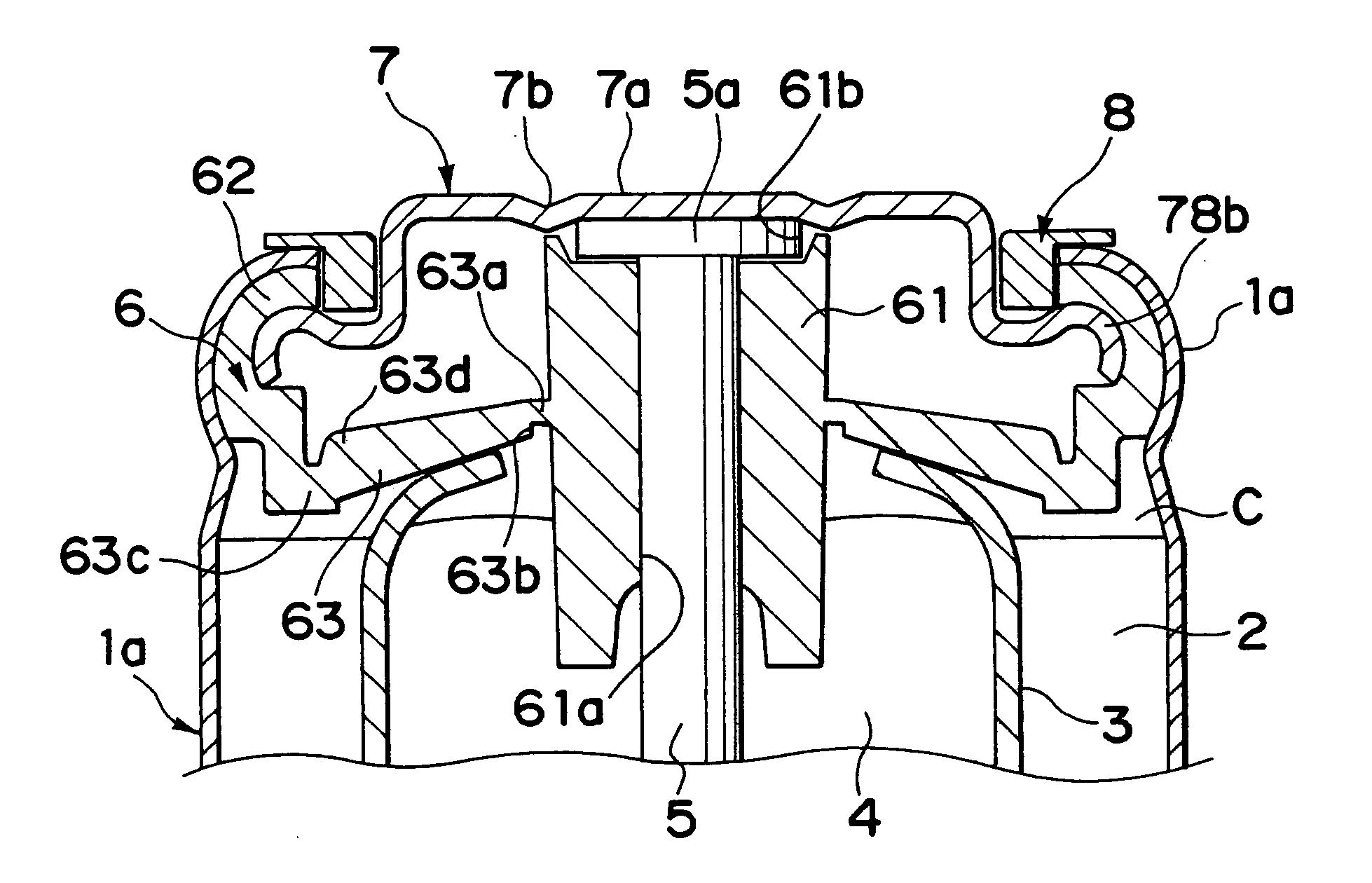
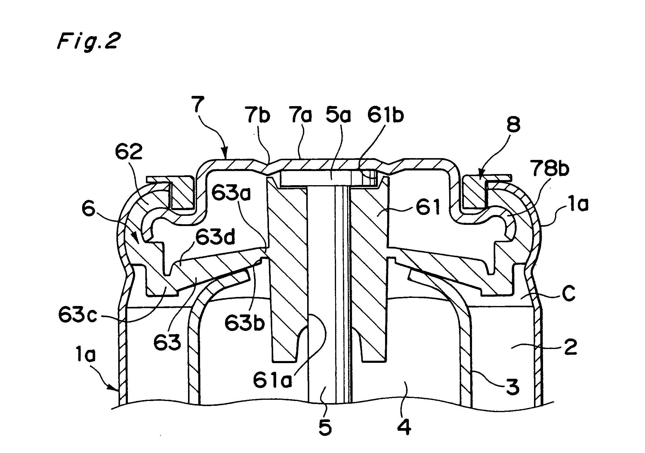
0066] In accordance with the inventions relating to claims 2, 3 and 4, in a cylinder type alkaline dry cell provided with a resin sealing member, only one sheet of metal plate that also serves as an anode terminal is used as a supporting member for supporting the sealing member with the inner circumferential side, and a predetermined curved portion is formed on the outer circumferential portion of this; therefore, it is possible to increase the actual inner capacity of the battery, and also to improve the leaking resistant property (liquid-sealing property or sealing property). Consequently, it becomes possible to achieve an alkaline dry cell with a high capacity that is free from solution leakage even under temperature changes, etc.
0068] In accordance with the inventions relating to claims 5, 6 and 7, in an alkaline dry cell provided with the resin sealing member, in the case when an anode terminal plate is used as the supporting member for supporting the resin sealing member with the inner circumferential side, even if the anode terminal plate is deformed in the sealing edge process, it is possible to reduce deviations in the dimension in the height direction of the battery due to the deformation.
0070] In accordance with the invention of claim 8, in an alkaline dry cell provided with the resin sealing member, it is possible to prevent a stress concentration onto the anti-explosion thin portion in the sealing member at the time of a lateral tightening sealing edge process, and consequently to reduce the load imposed on the thin portion.
0072] In accordance with the inventions relating to claims 9, 10 and 11, in an alkaline dry cell provided with a resin sealing member, it is possible to prevent the rupturing of the sealing member and the resulting scattering of the contents and generation of a big rupturing noise and the blocking of the gas releasing hole by the sealing member, and consequently to improve the reliability of the safety vale and the safety.

Problems solved by technology

However, in the case when the thickness of the external can made of a killed steel (aluminum killed steel) that is generally used in alkaline dry cell is reduced, problems tend to arise in which a difficult machining process is required and the external can tends to be deformed during a transporting process of the external can or a transferring process at the time of assembling the battery.
However, in the case when the thickness of the external can is set to be thinner than 0.18 mm, since the caulking strength of the sealing member is reduced, a new problem arises in which the inner electrolyte solution leaks from the sealing portion.
However, in the case when a thin external can having a thickness of not more than 18 mm, since the strength of the external can 1 decreases to an extent corresponding to the reduced thickness, the external can 1 fails to suppress the deformation of the resin sealing member, with the result that the electrolyte solution inside the battery comes to leak outside through the fine irregularities between the resin sealing member.
In particular, when the battery is subjected to an abrupt temperature change, the leak of the electrolyte solution tends to occur due to the swell and shrinkage of the material.
Since such a wasteful space S2 is located on the sealing member, the conventional sealing structure tends to have an unnecessary thickness of the sealing portion as a whole, resulting in a problem of a limited volume of the cell chamber C to be filled with a battery activating substance directly related to the charging capacity, that is, a limited inner volume of the battery.
However, from the viewpoint of manufacturing costs, a member that is thinner than the metal washer 107 (normally, one having a thickness of 0.4 mm) is used as the anode terminal plate 207; therefore, when the above-mentioned method is adopted, the anode terminal plate 207 is deformed upon caulking the sealing member 6, resulting in an insufficient force for tightening the outer circumferential portion 62 of the sealing member 6.
Deviations in the height of the battery cause problems.
For example, if there is a deviation in height on one battery is 0.5 mm, the maximum deviation of an apparatus housing six batteries in series with each other is 3 mm in the total length of the battery heights, with the result that the collector function of the apparatus is not properly exerted or the apparatus might fail to properly house the batteries.
However, in the conventional sealing construction in which the thickness of the connecting portion 63 is comparatively thin, and its portion on the outer circumferential section 62 and its portion on the boss section 61 side do not have so much a difference in the thickness, the sealing member 6 or its connecting section 63 is greatly deformed as a whole at the time of the sealing process by the lateral tightening operation, resulting in an excessive load on the anti-explosion thin portion (the actuation point of the safety valve) 63a in the connecting section 63, that is, a problem of too much stress on the corresponding thin portion 63a.
Moreover, in the even of an excessive discharging state, the safety valve fails to function properly, causing the sealing member 6 to rupture with the contents scattering with a big rupturing noise.
In an alkaline dry cell having the resin sealing member, in the case when a metal plate that also serves as an anode terminal plate as the supporting member for the sealing member is used as the supporting member for the sealing member, when the strength of a metal plate (anode terminal plate) located inside is weak when the sealing member is caulked, the force pressing the resin sealing member becomes weak, resulting in a state where the electrolyte solution leaks between the sealing member and the external can.
Therefore, when the curvature radius of the bent portion (curved portion 78b in the present invention) becomes too great, the amount of deformation in the fine area becomes small so that it is not possible to obtain the strength increase due to the process curing; in contrast, when the curvature radius of the bent portion becomes too small, the total volume of the deformed portion is small although the local amount of deformation becomes great, with the result that no strength increase by the process curing is expected.
However, when the angle of the curved portion 78b of the anode terminal plate 7 exceeds 180 degrees, it becomes impossible to carry out the press machining, resulting in an increase in costs; therefore, the angle is preferably set to not more than 180 degrees.
However, the degree exceeding 180 degrees fails to press the anode terminal plate 7 and the resin sealing member in the normal sealing edge system, making the members meaningless.

Method used


Image

  • Alkaline dry cell
  • Alkaline dry cell
  • Alkaline dry cell

Examples


example 5

[0133] Next, a cathode material (11.0 g), prepared by mixing manganese dioxide, graphite and water at a ratio of 92:5:3 (weight ratio) through an electrolytic method, was processed and molded into a cathode having a cylindrical shape measuring 9.1 mm in inner diameter, 13.3 mm in outer diameter and 43.0 mm in height, and this was inserted into an external can for a size "AA" alkaline dry cell. Thereafter, a groove was formed at a position 3.7 mm apart from the opening edge of the external can in the height direction. This arrangement is made so that when the sealing member is inserted later, the sealing member is held at the position of the groove so as not to be shoved deeper than the groove position. Moreover, inside the external can, pitch is applied from the opening edge to the position 3.7 mm in depth in the height direction so as to improve the adhering property between the external can and the sealing member.

[0134] Next, non-woven cloths, each made of vinylon and rayon having...

example 6

[0137] A size "AA" alkaline dry cell is formed in the same manner as Example 5 except that the average curvature radius of the curved portion on the outer circumferential portion of the metal plate (anode terminal plate) is set to 0.8 mm.

example 7

[0138] A size "AA" alkaline dry cell is formed in the same manner as Example 5 except that the average curvature radius of the curved portion on the outer circumferential portion of the metal plate (anode terminal plate) is set to 1.0 mm.


PUM

PropertyMeasurementUnit
thicknessaaaaaaaaaa
curvature radiusaaaaaaaaaa
thicknessaaaaaaaaaa

Abstract

The present invention discloses an alkaline dry cell with a high capacity having a superior liquid leak resistant property. In this alkaline dry cell, the thickness of the trunk portion of an external can is made thinner than 0.18 mm, and the thickness of the sealing edge portion of the external can is set to not less than 1.4 times the thickness of trunk portion. An anode terminal plate is used as a supporting member for a sealing member. Over the entire outer circumferential portion of the anode terminal plate is placed a curved portion having an average curvature radius of not more than 1 mm, which shows a virtually C-letter shape or an arc shape in its cross-section obtained by cutting the anode terminal plate through its center in the thickness direction.

Description

[0001] This application is a Divisional of co-pending application Ser. No. 09 / 941,564, filed on Aug. 30, 2001, and for which priority is claimed under 35 U.S.C. .sctn. 120; and this application claims priority of Application Nos. 2000-266336 filed in Japan on Sep. 1, 2000; 2000-266337 filed in Japan on Sep. 1, 2000; 2000-267701 filed in Japan on Sep. 4, 2000 and 2001-244779 filed in Japan on Aug. 10, 2001 under 35 U.S.C. .sctn. 119; the entire contents of all are hereby incorporated by reference1. FIELD OF THE INVENTION[0002] The present invention relates to a sealing technique of a cylindrical alkaline dry cell.2. DESCRIPTION OF THE BACKGROUND ART[0003] <Entire Schematic Structure of a Cylindrical Alkaline Dry Cell>[0004] For example, as illustrated in FIG. 15, a conventional cylindrical alkaline dry cell (dry battery) is provided with: a cathode 2 and an anode 4, a separator 3 placed between these electrodes, a nail-shaped anode collector rod 5 inserted into the anode 4 and ...

Claims


Application Information

Patent Timeline
Patent Type & Authority Applications(United States)
IPC IPC(8): H01M2/04H01M2/08H01M2/02H01M2/12H01M6/08
CPCH01M2/0421H01M2/1241H01M6/085H01M50/154H01M50/3425
Inventor URADE, MAKOTOTATEISHI, SHOICHIROKOIDE, KOJIIWAMOTO, SHINICHIUSHIJIMA, MINAJURO
Owner HITACHT MAXELL LTD
Why Eureka
Try Eureka