
Floor panel and method for manufacturing such floor panels

a technology for floor panels and manufacturing methods, applied in the field of floor panels, can solve the problems of complex and expensive procedure described in the german de 29 26 983, is less suitable for producing large volumes at a minimum cost price, and is particularly expensive equipment. , the technique is not suitable for the production of floor panels

Inactive Publication Date: 2004-12-23
FLOORING IND LTD
View PDF40 Cites 196 Cited by
  • Summary
  • Abstract
  • Description
  • Claims
  • Application Information

AI Technical Summary

Benefits of technology

[0020] When imitating wood, it is preferred that said indentations are provided in function of the wood pattern, and even better follow the lines of the wood pattern. In the case that said component then consists of a colour product, it is obtained that the pattern created by this colour product is optimally adapted to the underlying printed pattern of the decorative layer. In the case that said component does not consist of a colour product, but, as will be explained in the following, has other purposes, and, for example, consists of a colourless or almost colourless agent, the advantage is created that the presence of such component will be less apparent, as said agent is distributed over the surface of the floor panel in accordance with the underlying printed pattern.
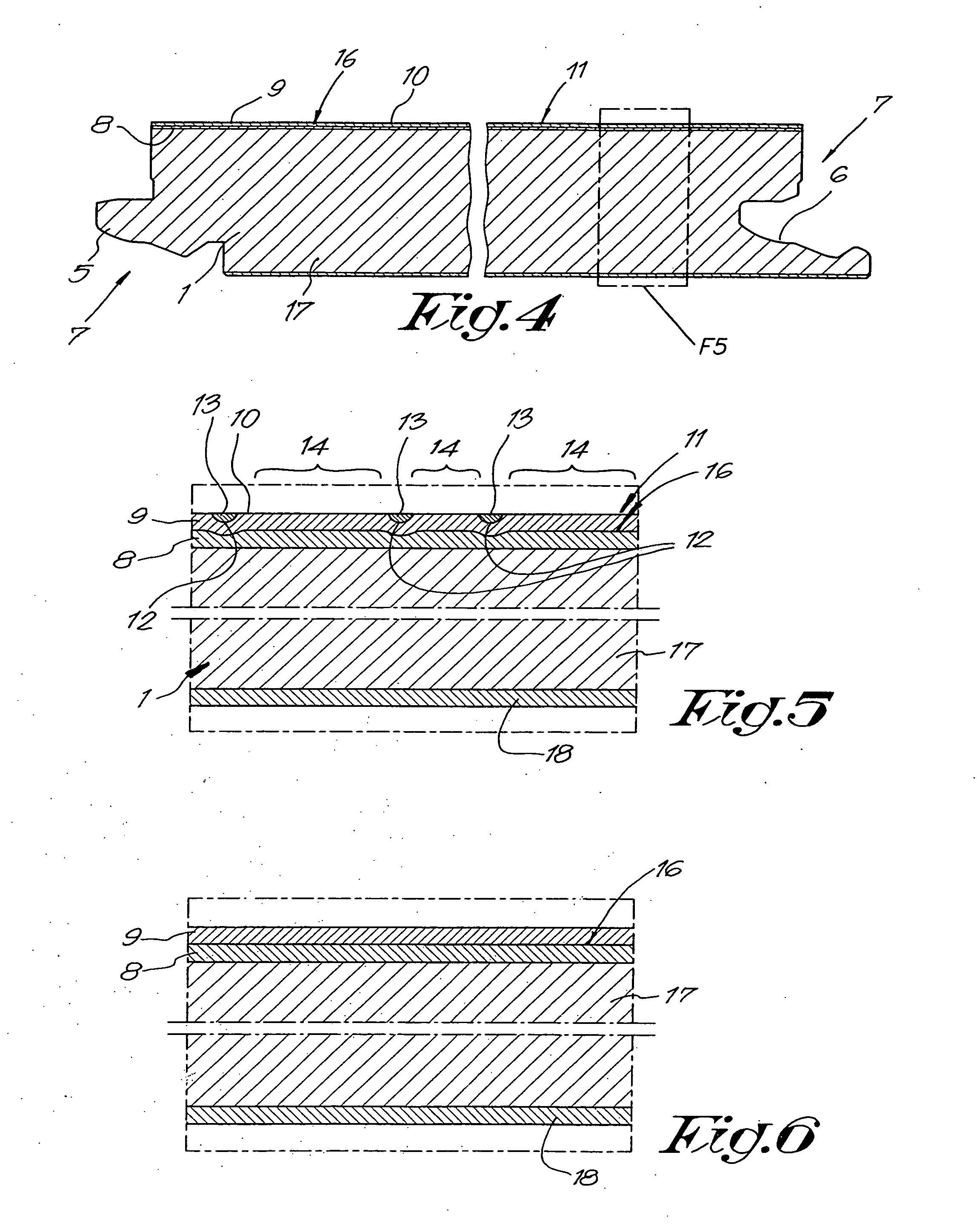
[0080] Finally, the invention also relates to a method for manufacturing a floor panel according to the invention, with the characteristic that this method comprises at least two main steps, on one hand, a first step wherein one or more basic layers, a decorative layer and a transparent so-called overlay, by means of a thermosetting synthetic material, are pressed together to a whole in a heated press, whereby, preferably simultaneously with pressing together, indentations are formed in the upper side, and, on the other hand, a second step, whereby said component is brought into the indentations. This method allows for a particularly smooth production, with relatively low production costs and in a manner suitable for mass production.

Problems solved by technology

This technique has the disadvantage that it is complex and, consequently, time-consuming and that it must be performed rather precisely, in consideration of the fact that two layers must be provided on top of each other and care must be taken in particular that the intermediate hardening is performed to a proper degree.
Another disadvantage consists in that one always has to work with at least two top layers, which can exert a disadvantageous influence on the clearness with which the pattern of the printed decorative layer finally is visible, and by which the pattern, formed by the paint in the indentations, is softened.
Thus, the complex and rather expensive procedure described in the German DE 29 26 983 is less suitable for producing larger volumes at a minimum cost price, as desirable in the production of floor panels.
This known technique requires particularly expensive equipment for, during pressing the laminate panels, simultaneously performing a printing action, which renders this technique thus little suitable for the production of floor panels.
As the colour product is provided during the formation of the indentations, as well as is formed by means of a printing process, moreover an appearance similar to printed matter is obtained, which renders the imitation effect less than optimum, at least for certain applications.
Further, it is also known to apply techniques whereby the application of colour products on certain locations in recesses is coupled specifically to particular surface treatments, as a consequence of which the typical characteristics of the normal panel surface can not be guaranteed any longer.
Practice has shown that in such specific application, it is difficult to arrive at a good imitation of a really coloured wooden floor.
The pure paper itself as such is white, however, after impregnation with resin and after pressing the overlay, it becomes almost colourless.
So, for example, it is known that it is difficult to realize very light decors, for example, so-called "crus", as well as very dark decors in a proper manner, as with the techniques known up to now, whereby the decor is determined substantially by the printed decorative layer, the richness of the obtained decor often is considerably less than intended.
On one hand, this poses the problem that such thick printing is difficult to perform.
On the other hand, such thick printing results in that the decorative layer hardly takes up any resin and the necessary resin treatment or impregnation is rendered difficult.
With laminate tiles, it is rather difficult to imitate thin joints by means of printing, in particular when joints of half the width must be provided along the peripheral edge of a floor panel.
The least divergence between the printed pattern and the real edge of the floor panel then results in that the printed joint either completely drops off the floor tile, or appears completely on the floor tile, at a distance to the edge of the floor tile, which renders such floor tiles unusable.
Also if the printed joints are provided such that they extend transversely over such final floor tile, the application of such printed narrow joints results in that divergences, more particularly a shifting of the printed pattern in respect to the edge of the floor panel, will be very apparent, such because then it may occur that the printed joints of adjoining floor tiles are shifted completely in respect to each other, which is experienced as very annoying.
Tests, however, have shown that this leads to a very bad optical result.
Furthermore, when wet-cleaning such tiles, moisture might penetrate between the floor tiles, which then is immediately taken up under the decorative layer into the core material, which results in that the core material swells up and pushes the decorative layer, as well as the top layer present thereabove, upward.
This results in that the upper surface, at the location of the upwardly pushed edges, wears faster, which finally leads to the occurrence of ugly edges.
Hereby, it is noted that this risk is rather high with laminate tiles imitating stone tiles, as the users of such laminate tiles often have the habit to regularly wet-clean these tiles, just as real stone floor tiles.
The inventor has found that by polishing such top layer, surprisingly beautiful glossy surfaces can be realized, such contrary to the general expectance that such top layer, when being excessively polished, would be removed and / or damaged.

Method used


Image

  • Floor panel and method for manufacturing such floor panels
  • Floor panel and method for manufacturing such floor panels
  • Floor panel and method for manufacturing such floor panels

Examples


Embodiment Construction

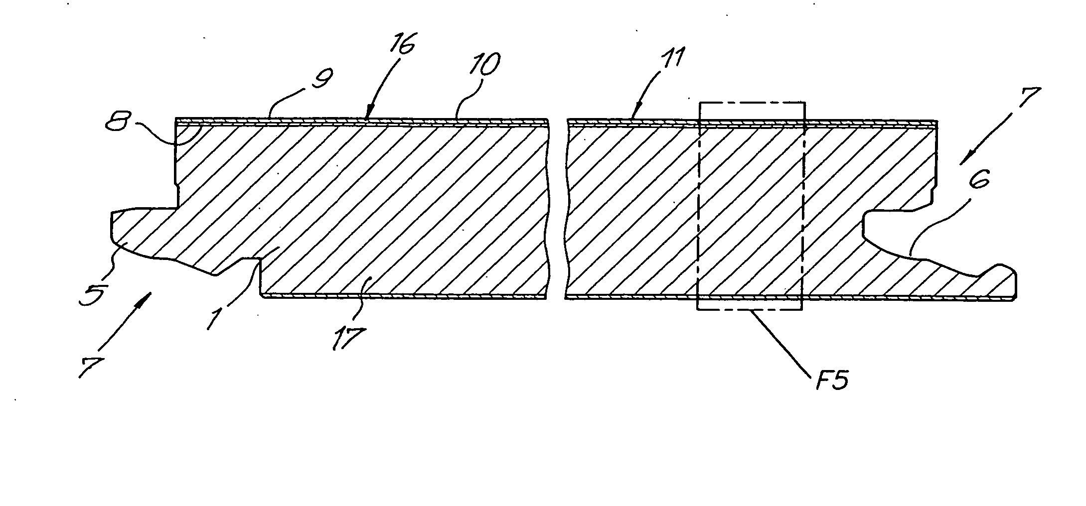
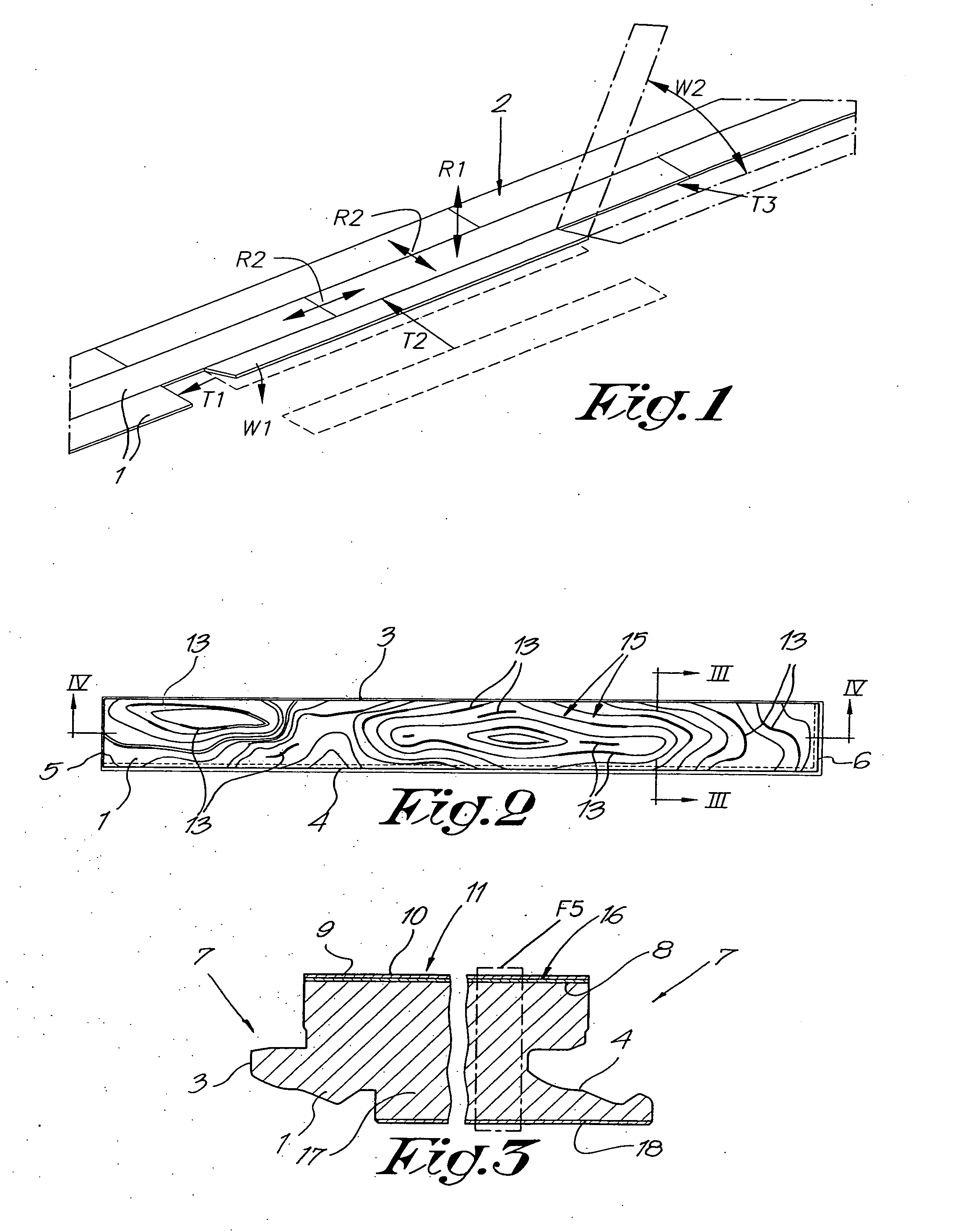
[0098] As represented in FIGS. 1 and 2, the invention relates to floor panels 1, more particularly laminate panels, for forming a floor covering 2.

[0099] In the represented example, the floor panels 1 are rectangular, however, it is clear that according to variants not represented, they also can have another shape and can be, for example, square or polygonal, such as hexagonal or octagonal.

[0100] Preferably, the floor panels 1 are provided at least at two opposite edges 3-4, and even better, as represented in FIGS. 2 to 4, at both pairs of edges 3-4, 5-6, respectively, with coupling means 7, by which several of such floor panels 1 can be mutually coupled, such that these coupling means 7, in coupled condition, offer a locking in vertical as well as horizontal directions.

[0101] Such coupling means 7, which, as known, allow to couple the floor panels 1 without glue, as well as uncouple them again, as such are well known from the state of the art and are described, amongst others, in t...


PUM

PropertyMeasurementUnit
Lengthaaaaaaaaaa
Coloraaaaaaaaaa
Dimensionaaaaaaaaaa

Abstract

Floor panel, of the type consisting of a laminate panel which comprises at least a printed decorative layer (8) and a top layer (9) forming the upper surface (10) of the floor panel (1), more particularly a so-called overlay, whereby this top layer (9), or, thus, overlay, is realized on the basis of a thermosetting resin, characterized in that in the upper side (11) of the floor panel (1), indentations (12) are formed and in that at last in a number of these indentations (12), a component (13) is provided, which is obtained in that it has been provided in those indentations (12) after the provision of the indentations (12).

Description

[0001] 1. Field of the Invention[0002] This invention relates to a floor panel, as well as to a method for manufacturing such floor panel.[0003] In particular, the invention relates to so-called laminate panels for forming a floor covering.[0004] It is known that in such laminate panels for floors, the appearance of wood, more particularly parquetry or the like, or the appearance of stones or ceramic tiles, is imitated by providing the floor panels, in the proximity of their upper surface, with a decorative layer printed with a pattern, for example, a wood pattern or tile pattern, over which a transparent synthetic layer is provided.[0005] Usually, the printed decorative layer consists of printed paper, whereas the clear synthetic layer normally consists of a synthetic resin or one or more transparent or clear resin-impregnated material layers, for example, paper layers, in which possibly also products can be incorporated in order to enlarge, for example, the wear and tear resistanc...

Claims


Application Information

Patent Timeline
IPC IPC(8): B32B3/30B32B27/04B44C1/20B44C1/22B44C1/24B44C5/04B44F9/02B44F9/04E04F15/02E04F15/04
CPCB32B3/30B32B27/04B44C1/20B44C1/24B44C5/0469B44F9/02B44F9/04E04F15/02E04F15/02005E04F15/02033E04F15/04E04F2201/0115E04F2201/0153E04F15/02011E04F15/02016B32B2260/046B32B2260/028B32B2307/554B32B2419/04B32B27/06
Inventor THIERS, BERNARD PAUL JOSEPHDE BOE, LODE HUBERT LIEVENVANHASTEL, LUC DIRK DANIEL
Owner FLOORING IND LTD
Learn More