Heat controlled optoelectrical unit

a technology of optoelectric units and heat control, which is applied in the direction of thermoelectric devices, semiconductor lasers, instruments, etc., can solve the problems of non-trivial optimization problems, increased heat power loss with increasing processing speed/bitrate, and relatively large power loss of laser modules in particular

Inactive Publication Date: 2004-12-23
II VI DELAWARE INC
View PDF9 Cites 7 Cited by
  • Summary
  • Abstract
  • Description
  • Claims
  • Application Information

AI Technical Summary

Benefits of technology

[0009] This design is most advantageous, since it combines an efficient usage of the circuit board area with a competent cooling of the optoelectrical capsules.
[0021] According to a still further preferred embodiment of the invention, the secondary heat sink is also adapted to receive heat energy from at least one circuit element outside the coverage area of the primary heat sink. Thus, the heat sink arrangement's cooling capabilities become effective for other units than the optoelectrical capsules, which generally is desirable. Preferably, a thermo conductive gap filler is included between said at least one circuit element and the secondary heat sink. This namely both enhances the thermo conductive coupling there between and accomplishes a good mechanical fit between the capsule and the heat sink.

Problems solved by technology

However, the photodetection module and the laser module in particular produce a relatively large amount of power losses in the form of heat energy, which must be transported away from the equipment in order to maintain an acceptable working temperature.
Classically, the heat power losses increase with increased processing speeds / bitrates.
Hence, increasing the ratio of processing capacity per volume or area unit implies a non-trivial optimization problem.

Method used


Image

  • Heat controlled optoelectrical unit
  • Heat controlled optoelectrical unit
  • Heat controlled optoelectrical unit

Examples


Embodiment Construction

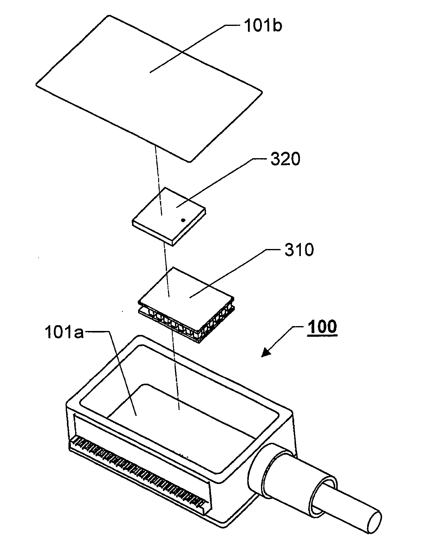
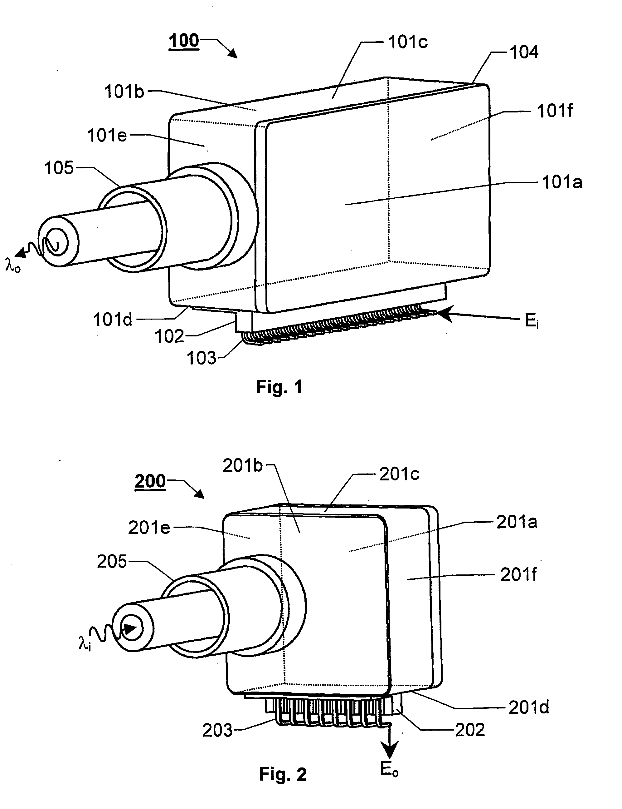
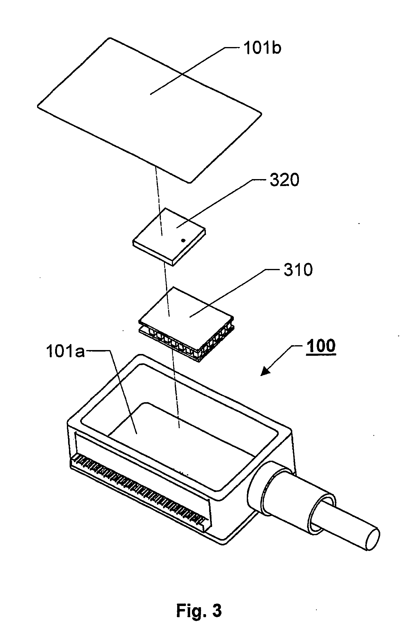
[0031] Conventionally, the optoelectrical units (such as lasers and photodetectors) in optoelectrical transceivers have been oriented with their largest side in parallel with the circuit board on which they are mounted. A largest possible interface area has thereby been accomplished towards at least one heat sink being placed either below, above or both below and above the circuit board. This design, however, results in a relatively large footprint for each optoelectrical unit, which in turn consumes valuable circuit board area that could have been used by other units. Therefore, the present invention proposes that the optoelectrical units instead be placed on their edges, i.e. with a capsule side having a comparatively small area towards the circuit board. FIG. 1 shows a first example of this strategy, where a capsule 100 containing a laser unit stands on one of its relatively small area sides 101d. The laser capsule 100 is presumed to have the general shape of a rectangular parall...


PUM


Abstract

The present invention relates to heat control and cooling of an optoelectrical unit, which converts between electrical and optical signal formats. The optoelectrical unit contains at least one optoelectrical capsule positioned on a circuit board. A primary heat sink is adapted to receive heat energy dissipated from the capsule. The capsule is oriented on the circuit board, such that it presents a relatively small footprint thereon and, at the same time, rises relatively large area sides, which do not face directly towards the circuit board. The primary heat sink has at least one cavity, which is adapted to the shape and dimensions of the capsule, such that the cavity contains at least one capsule. The primary heat couples thermally well to the capsule. Furthermore, the capsules assist in aligning the primary heat sink in its intended position.

Description

THE BACKGROUND OF THE INVENTION AND PRIOR ART[0001] The present invention relates generally to heat control and cooling of optical communication equipment. More particularly the invention relates to an optoelectrical unit for converting information signals between an electrical signal format and an optical signal format according to the preamble of claim 1.[0002] Optical communication systems transport information in the form of modulated light signals. A laser module, e.g. a semiconductor laser (laser=light amplification by stimulated emission of radiation) in a signal transmitter unit is here normally used in order to accomplish the optical signals based on electrical ditto, and a photodetection module, e.g. a photodiode, in a signal receiver unit typically converts the optical signals back into electrical signals again. In most cases, the signal transmitter and a corresponding signal receiver are co-located to form an optoelectrical transceiver unit. These units, in turn, normall...

Claims


Application Information

Patent Timeline
Patent Type & Authority Applications(United States)
IPC IPC(8): G02B6/42H01L35/00H01S5/024
CPCG02B6/4277G02B6/4292G02B6/4269H01S5/02415H01L35/00H10N10/00
Inventor LINDBERG, LARS
Owner II VI DELAWARE INC
Why Eureka
Try Eureka