Vehicle control apparatus

a technology for controlling apparatus and vehicles, applied in the direction of electric control, ignition automatic control, machines/engines, etc., can solve the problems of a large amount of change of output torque, automatic transmission having a plurality, and transmission may suffer from a shock during the transmission period

Inactive Publication Date: 2004-12-23
TOYOTA JIDOSHA KK
View PDF8 Cites 30 Cited by
  • Summary
  • Abstract
  • Description
  • Claims
  • Application Information

AI Technical Summary

Benefits of technology

[0014] Where the drive power source device includes at least one of an engine and an electric motor, the first controlling portion preferably includes at least one of an ignition-timing control device operable to effect an ignition-timing control of adjusting an ignition timing of the engine, and an electric-motor-torque control device operable to effect an electric-motor-torque control of controlling a torque of the electric motor. Accordingly, the drive-power-source torque can be controlled with an excellent response characteristic.
[0015] The second controlling portion preferably includes at least one of an electronic-throttle-valve control device operable to effect an electronic-throttle-valve control of controlling an opening angle of an electronically controlled throttle valve of the engine, a supercharging-pressure control device operable to effect a supercharging-pressure control of controlling a supercharging pressure of a supercharger of the engine, and a valve-device control device operable to effect an engine-cylinder control of controlling the number of operable cylinders of the engine. These devices are capable of continuously controlling the drive-power-source torque for a relatively long time.

Problems solved by technology

In a vehicle including an automatic transmission having a plurality of operating positions having respective different speed ratios, wherein a selected one of the operating positions is automatically selected, the transmission may suffer from a shock during a shifting action thereof.
Unlike a continuously variable transmission, an automatic transmission having a plurality of operating positions having respective different speed ratios suffers from a considerably large amount of change of its output torque before and after a shifting action thereof, due to a non-smooth abrupt change of the speed ratio from a value before the shifting action to a value after completion of the shifting action.
The conventional engine output control apparatus is not satisfactory in its capability to minimize a drawback that the drivability of the vehicle tends to be deteriorated due to a considerably large amount of change of the vehicle drive force upon a shifting action of the automatic transmission.
These devices are capable of continuously controlling the drive-power-source torque for a relatively long time.

Method used


Image

  • Vehicle control apparatus
  • Vehicle control apparatus
  • Vehicle control apparatus

Examples


Embodiment Construction

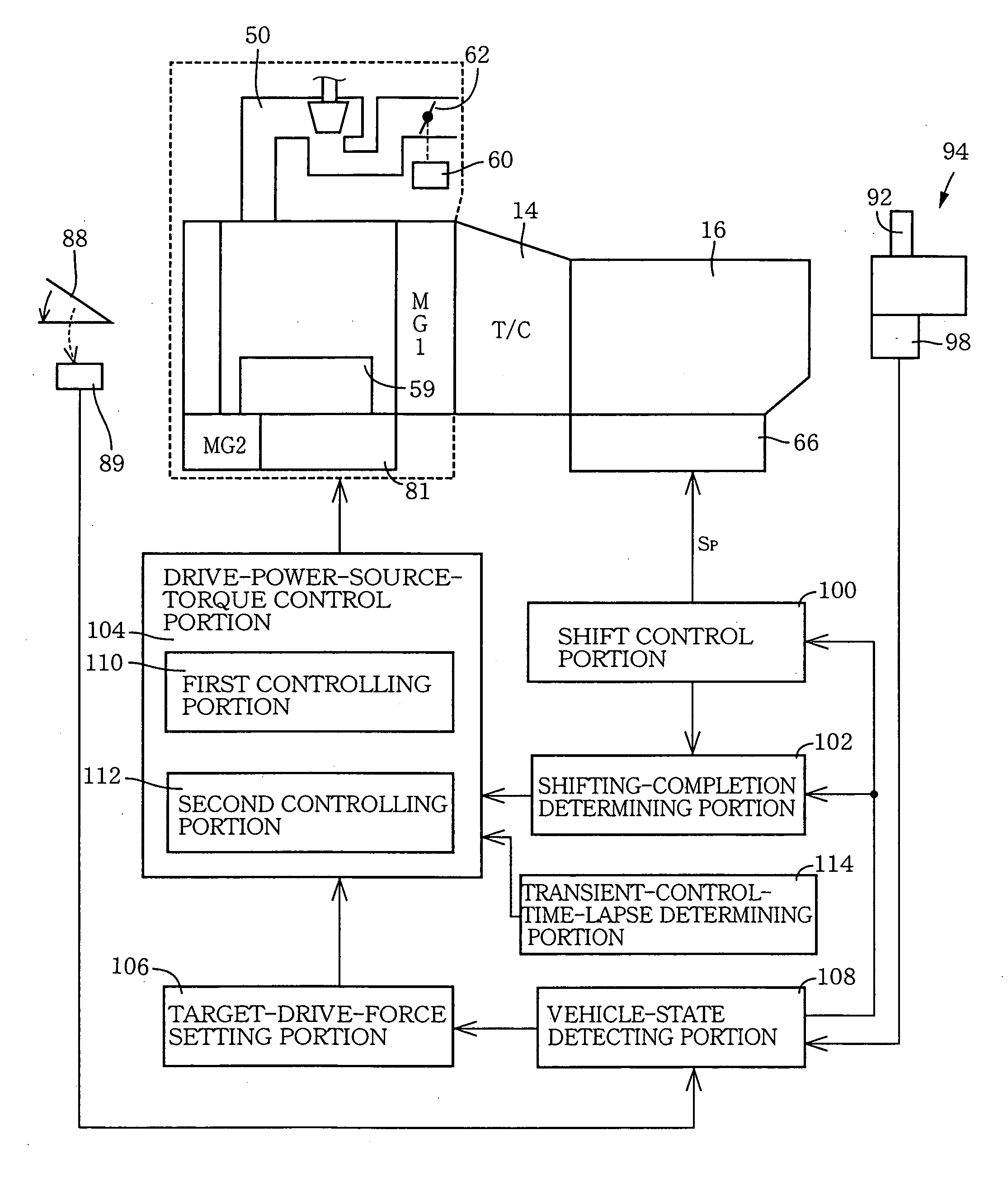
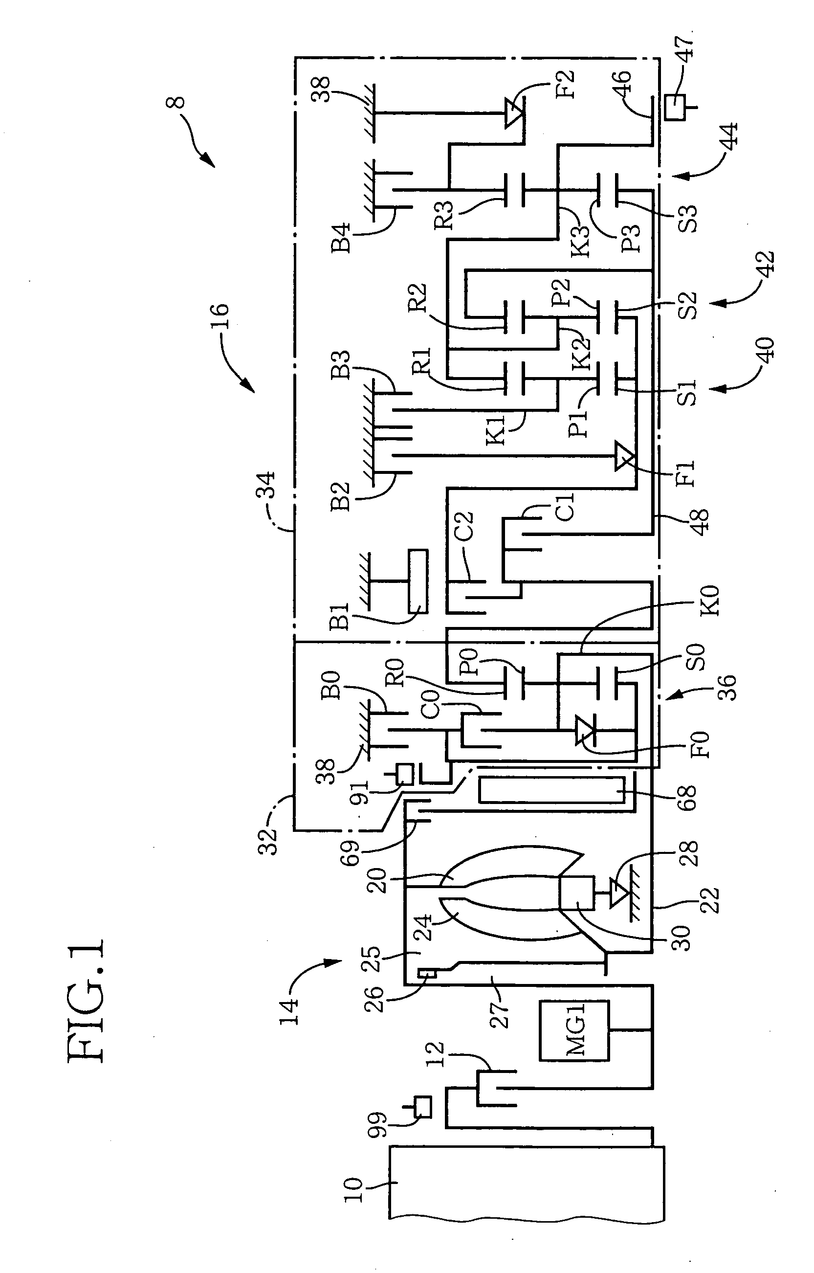
[0035] Referring first to the schematic view of FIG. 1, there is shown an arrangement of a drive system 8 of a hybrid vehicle that is controlled by a vehicle control apparatus constructed according to one embodiment of this invention. The vehicle drive system 8 includes an internal combustion engine 10, an input clutch 12, a fluid-operated power transmitting device in the form of a torque converter 14, and an automatic transmission 16. The engine 10 constitute a part of a drive power source of the vehicle. An output of the engine 10 is transmitted to the automatic transmission 16 through the input clutch 12 and torque converter 14, and is transmitted from the automatic transmission 16 to drive wheels through a differential gear device and drive axles, which are well known in the art and are not shown. Between the input clutch 12 and the torque converter 14, there is disposed the above-described first motor / generator MG1, which functions as an electric motor and an electric generator...


PUM


Abstract

An apparatus for controlling an automotive vehicle having a drive power source, a transmission having a plurality of operating positions that are selectively established, and a manually operable vehicle accelerating member, the apparatus including a target-drive-force setting portion operable to determine a target vehicle drive force on the basis of an operating amount of the accelerating member and a presently selected one of the positions of the transmission, such that the determined target vehicle drive force permits a smooth change of an actual vehicle drive force with a change of the operating amount of the vehicle accelerating member, irrespective of a shifting action of the transmission, a first controlling portion having a relatively high operating response and operable to effect a transient control of a torque of the drive power source so that the actual vehicle drive force coincides with the target vehicle drive force after the shifting action of the transmission, and a second controlling portion having lower operating response than the first controlling portion but is capable of continuously controlling the torque of the drive power source, the second controlling portion being operable to effect a continuous control of the torque of the drive power source following the transient control by the first controlling portion, so that the actual vehicle drive force coincides with said target vehicle drive force after the shifting action of the transmission.

Description

[0001] This application is based on Japanese Patent Application No. 2003-174039 filed on Jun. 18, 2003, the contents of which are incorporated hereinto by reference.[0002] 1. Field of the Invention[0003] The present invention relates in general to a vehicle control apparatus including a drive-power-source-torque control portion for controlling a torque of a drive power source (e.g., engine) for a vehicle, and more particularly to techniques for determining a target vehicle drive torque on the basis of an operating amount of a manually operated vehicle accelerating member and a selected operating position of a transmission having respective different speed ratios, so as to permit a smooth change of the vehicle drive force with a change of the operating amount of the vehicle accelerating member, for thereby improving the drivability of the vehicle, irrespective of a shifting action of the transmission, that is, irrespective of a non-smooth change of the speed ratio of the transmission...

Claims


Application Information

Patent Timeline
Patent Type & Authority Applications(United States)
IPC IPC(8): B60K6/48B60W10/06F02P5/15B60W10/08B60W20/00F02D11/10F02D13/02F02D17/02F02D23/00F02D29/00F02D29/02F02D41/02F02D41/04F02D43/00F16H59/08F16H59/18F16H61/02F16H61/04F16H61/68F16H61/684F16H61/686F16H63/50
CPCB60K6/48Y10T477/67B60L2240/441B60W10/06B60W10/08B60W20/00B60W2510/0638B60W2540/10F02D11/105F02D41/023F02D2250/18F16H61/0437F16H63/502Y02T10/6221Y02T10/6286F16H2063/506Y10T477/68Y10T477/676Y10T477/23Y10T477/675Y10T477/677Y10T477/679B60K6/547Y02T10/62B60W20/10
Inventor TABATA, ATSUSHIHOSHINO, AKIRATANAKA, YOSHIKAZUKONDO, MASAMI
Owner TOYOTA JIDOSHA KK
Why Eureka
Try Eureka