Sole structure for a shoe

a technology of sole body and lateral direction, which is applied in the direction of uppers, bootlegs, stiffners, etc., can solve the problems of bending of the sole body, and achieve the effect of improving the bendability of the entire sole body in the lateral direction

Inactive Publication Date: 2005-01-06
MIZUNO CORPORATION
View PDF7 Cites 77 Cited by
  • Summary
  • Abstract
  • Description
  • Claims
  • Application Information

AI Technical Summary

Benefits of technology

[0038] The cavity may penetrate the sole body in a lateral direction so that bendability of the entire sole body in a lateral direction can be improved.

Problems solved by technology

In other words, loading of the weight of a shoe wearer causes bending of the sole body.

Method used


Image

  • Sole structure for a shoe
  • Sole structure for a shoe
  • Sole structure for a shoe

Examples


first embodiment

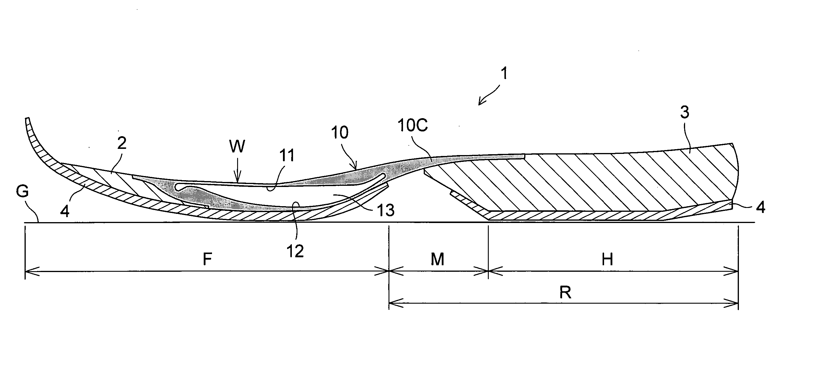
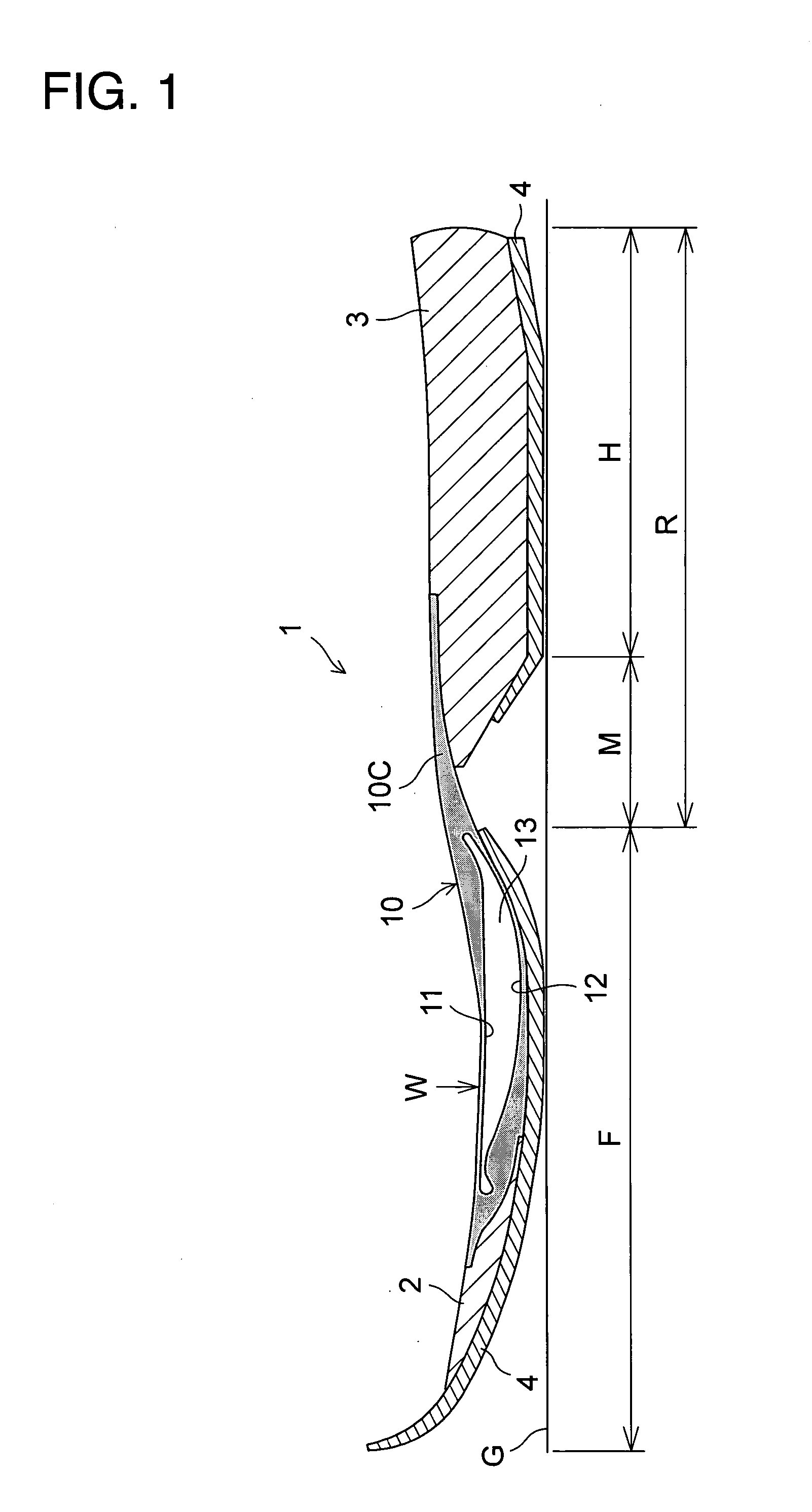
[0061] FIGS. 1 to 5 show a sole assembly of the present invention. As shown in FIG. 1, a sole assembly 1 in use for a shoe includes a sole body that is comprised of a sole body forefoot portion 2 disposed mainly at a forefoot region F of the sole assembly 1 and a sole body heel portion 3 disposed at a heel region H to a midfoot or plantar arch region M of the sole assembly 1. An outsole 4 that contacts the ground G is attached to the bottom surface of the sole body. A region including the heel region H and the midfoot region M of the sole assembly 1 is herein referred to as a ‘rearfoot’ region R.

[0062] The sole body may be formed of a soft elastic material. Specifically, thermoplastic synthetic resin foam such as ethylene-vinyl acetate copolymer (EVA), thermosetting resin foam such as polyurethane (PU), or rubber material foam such as butadiene or chloroprene rubber is used.

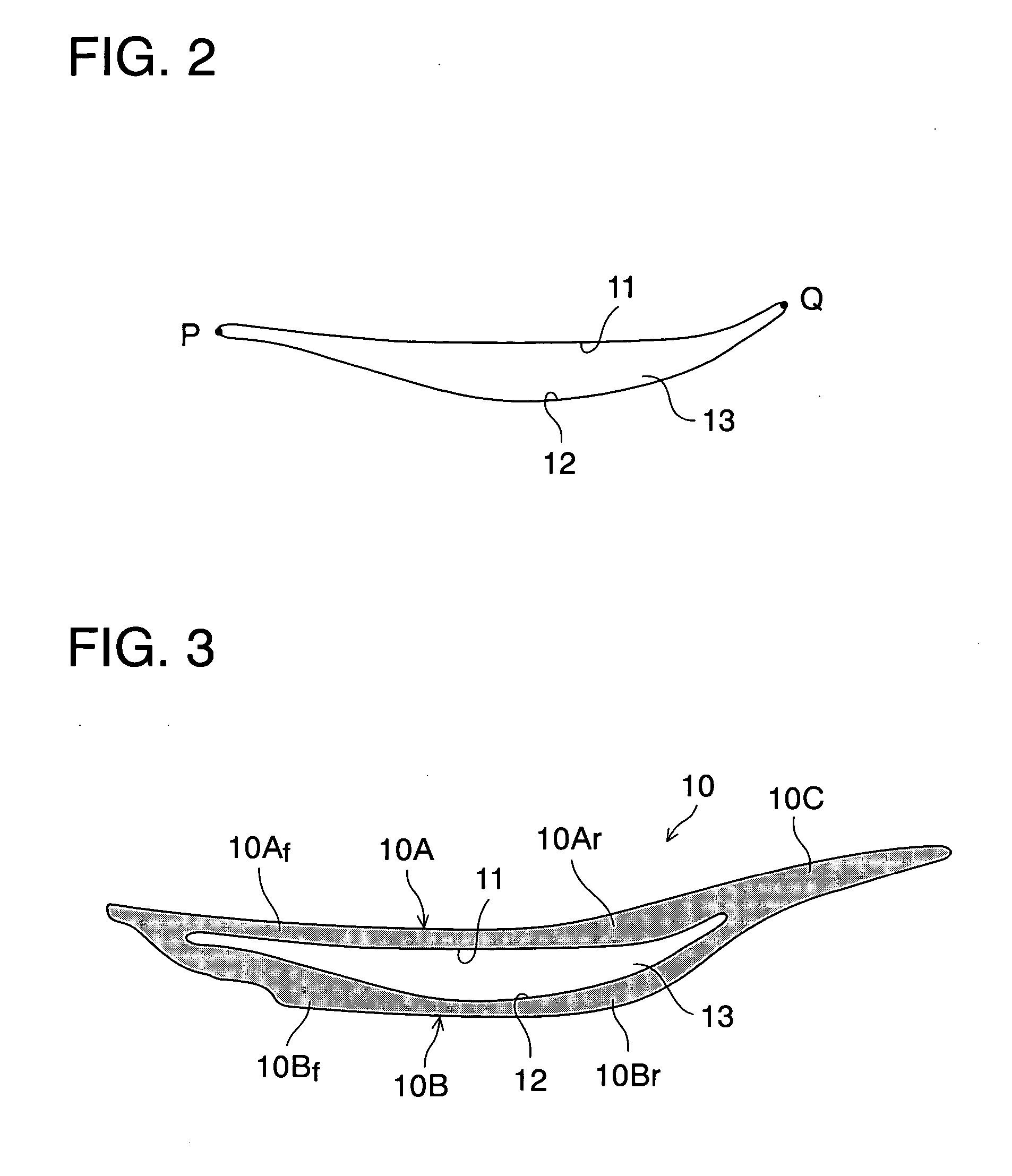
[0063] Mainly at the forefoot region F of the sole assembly 1, there is provided an elastic body 10 having a ...

second embodiment

[0079]FIGS. 6 and 7 show a sole assembly of the present invention. In these drawings, like reference numbers indicate identical or functionally similar elements.

[0080] As shown in FIG. 6, a soft elastic block 20 such as foamed material (e.g. sponge) softer than the sole body 2 is interposed at least at a portion of the cavity 13 of the elastic body 10.

[0081] In this embodiment, the way of deformation of the first and second curved surface 11, 12 such as the amount of elastic deformation or restorative speed after elastic deformation of the first and second curved surface 11, 12 can be adjusted by suitably changing expansion rate of the elastic block 10 inserted into the cavity 13 or the inserted position thereof. In addition, FIG. 7 illustrates the state in which the first and second curved surface 11, 12 is elastically deformed similarly to the state shown in FIG. 4.

third embodiment

[0082] FIGS. 8 shows an elastic structure constituting a sole assembly of the present invention. In the drawing, like reference numbers indicate identical or functionally similar elements.

[0083] In the above-mentioned first and second embodiments, the elastic body 10 was shown that has a cavity 13 formed of the first and second curved surface 11, 12, whereas in this third embodiment, an elastic structure shown in FIG. 8 is used that comprises a band-shaped first and second plate 10A′, 10B′ whose opposite ends are coupled to each other. That is, in this case, a first curved surface 11 is formed of an inner surface of the first plate 10A′ and a second curved surface 12 is formed of an inner surface of the second plate 10B′.

[0084] The elastic structure is preferably formed of a single loop member in which a first plate 10A′ and a second plate 10B′ are integrally formed with each other. This elastic structure is formed of a similar material to the elastic body 10 of the first and secon...


PUM


Abstract

A hard elastic body (10) having a longitudinally extending cavity (13) formed therein is provided mainly at a forefoot region (F) of a sole body. The cavity (13) is formed of a first curved surface (11) extending curvedly in a longitudinal direction and a second curved surface (12) disposed under the first curved surface (11) and extending curvedly in a longitudinal direction as well. A front and rear end of the second curved surface (12) is connected to a front and rear end of the first curved surface (11) respectively and an intermediate portion of the second curved surface (12) is spaced apart downwardly from an intermediate portion of the first curved surface (11). A path (PQ1) between the front and rear end of the first curved surface (11) is substantially equal to a path (PQ2) between the front and rear end of the second curved surface (12). When the first curved surface (11) is pressed downwardly, the sole body is deformed in such a way that a rear foot region (R) of the sole body is lifted upwardly.

Description

BACKGROUND OF THE INVENTION [0001] The present invention relates to a sole structure for a shoe, and more particularly, to an improvement in bendability of a sole forefoot portion. [0002] A sole of a shoe is typically formed of a soft elastic material to achieve cushioning properties and bendability or flexibility is also required at a sole forefoot portion to get a smooth ‘ground-kicking’ of the sole forefoot portion during running or walking. In a prior art shoe, bendability or flexibility of a sole forefoot portion is achieved by decreasing the thickness of the sole forefoot portion or forming a laterally extending bent groove at the sole forefoot portion. [0003] However, in a conventional sole assembly, bending motion of a forefoot of a shoe wearer is transmitted to a sole forefoot portion of a shoe via an upper of the shoe at the time of bending of the forefoot portion of the shoe wearer. That is, a conventional sole assembly is not structured in such a way that bending motion ...

Claims


Application Information

Patent Timeline
Patent Type & Authority Applications(United States)
IPC IPC(8): A43B13/12A43B13/14A43B13/16A43B13/18
CPCA43B7/141A43B7/142A43B7/1425A43B7/1435A43B13/181A43B13/026A43B13/12A43B13/141A43B13/16A43B7/1445
Inventor KIMURA, TAKAYAKANEKO, YASUNORITAKESHITA, TAKESHISUZUKI, KAZUHIKOARAKI, KENJISATO, NATSUKIODA, TAKAOKITA, KENJIRO
Owner MIZUNO CORPORATION
Why Eureka
Try Eureka