Combined pre-treatment process for enabling feed material to be charged in direct reduction processes

a pre-treatment process and direct reduction technology, applied in climate sustainability, furnace types, furnace types, etc., can solve problems such as internal stress release, and achieve the effects of reducing the generation of fines

Active Publication Date: 2005-01-06
VALE LIMITED
View PDF14 Cites 3 Cited by
  • Summary
  • Abstract
  • Description
  • Claims
  • Application Information

AI Technical Summary

Benefits of technology

[0009] The present invention pre-treats the feed material introduced to the direct reduction furnace, significantly reducing generation of fines. The invented process can be modified to be effective with a particular plant design.
[0010] It is known that sedimentary lump ores, such as naturally humid Corumba lump ore, have very little resistance to the combined effect of thermal shock and reduction at low temperatures, which fragment the lump, eventually resulting in a very high generation of fines (on the order of 40% of the initial weight) within the direct reduction furnace. It has now been determined that a combined pretreatment of Corumba lump ore will cause a dramatic reduction in fines generation: pretreatment combines storage in piles followed by predrying at low temperatures (<200 C.), which is followed by low-temperature reduction in the furnace, the furnace having an enhanced thermal profile, with an increase in its local and average temperatures. The cause of such mechanical weakness is attributed to the microstructure of Corumba lump ore, which is mainly constituted of micropores, as opposed to the widely known metamorphic lump ores, wherein the pores are usually larger in size. Therefore, an accentuated thermal shock drives out the retained moisture at a very high rate, resulting in the weakening of the microstructure and eventually leading to the generation of fines. In addition, it is understood within the direct reduction industry that reduction in the temperature of 500-750 C. within the furnace zone above the reduction zone results in low temperature decrepitation. The applicants have determined that the less reduction of ore that occurs at a temperature less than 800 C., the fewer fines are generated due to low temperature decrepitation. To achieve this, an enhanced thermal profile is provided in the direct reduction furnace, which increased the average...

Problems solved by technology

Furthermore, some sedimentary lump ores, due to their peculiar morphology,...

Method used


Image

  • Combined pre-treatment process for enabling feed material to be charged in direct reduction processes
  • Combined pre-treatment process for enabling feed material to be charged in direct reduction processes
  • Combined pre-treatment process for enabling feed material to be charged in direct reduction processes

Examples


Embodiment Construction

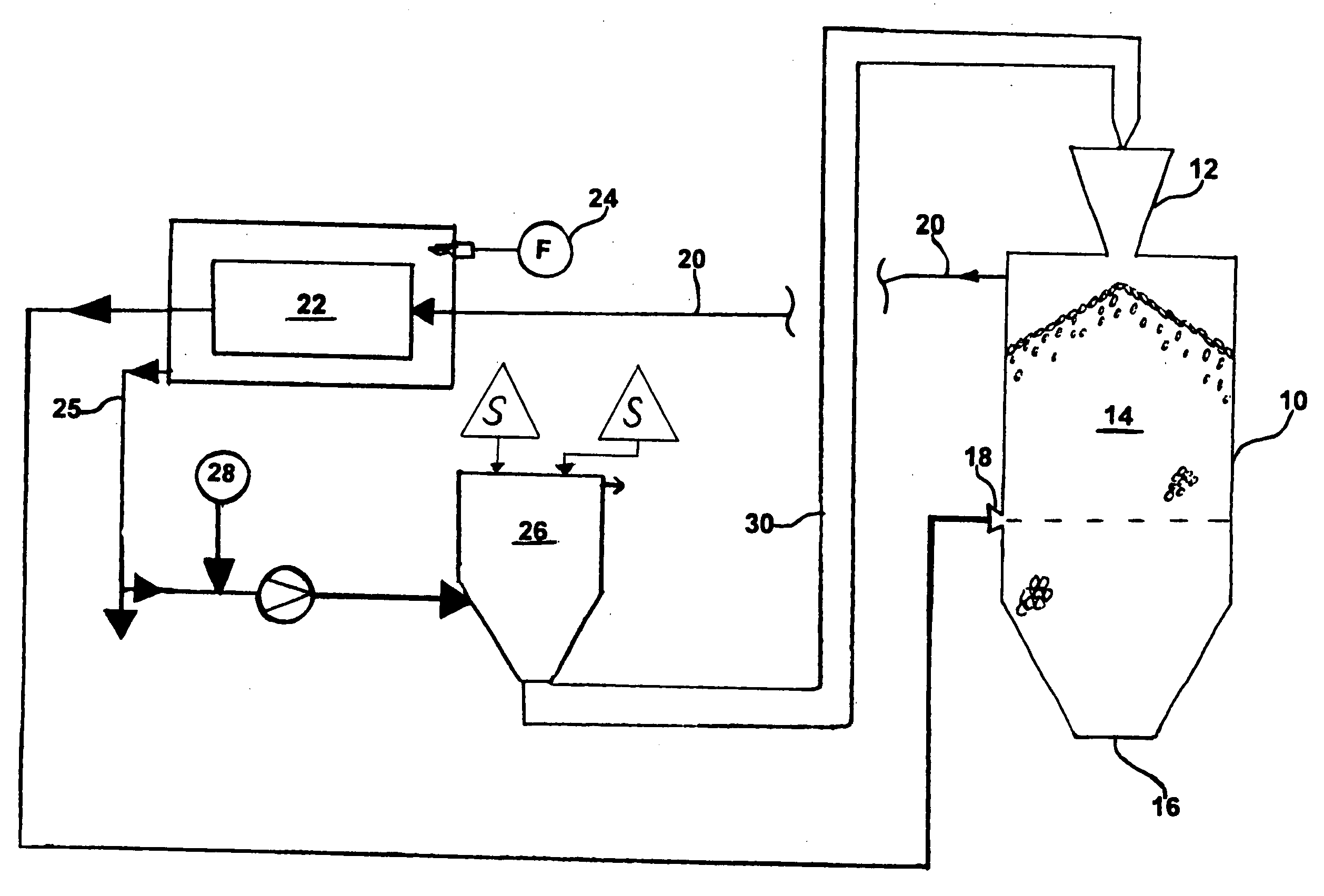
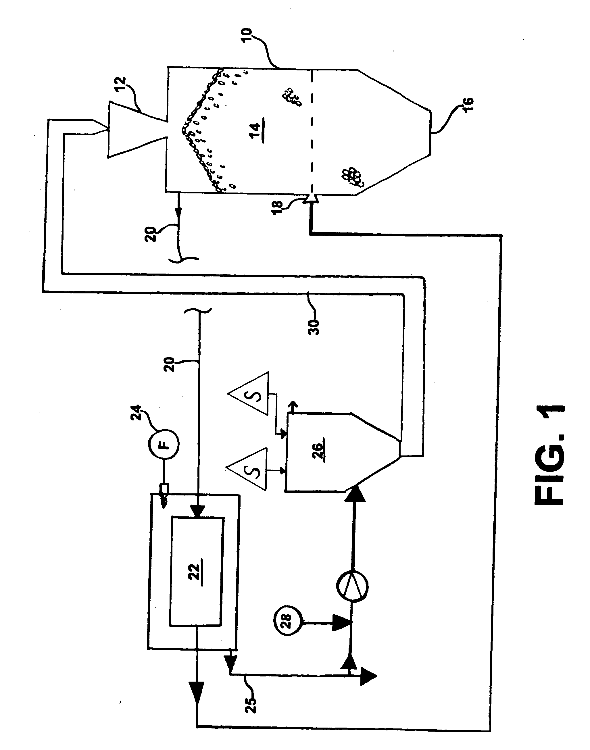
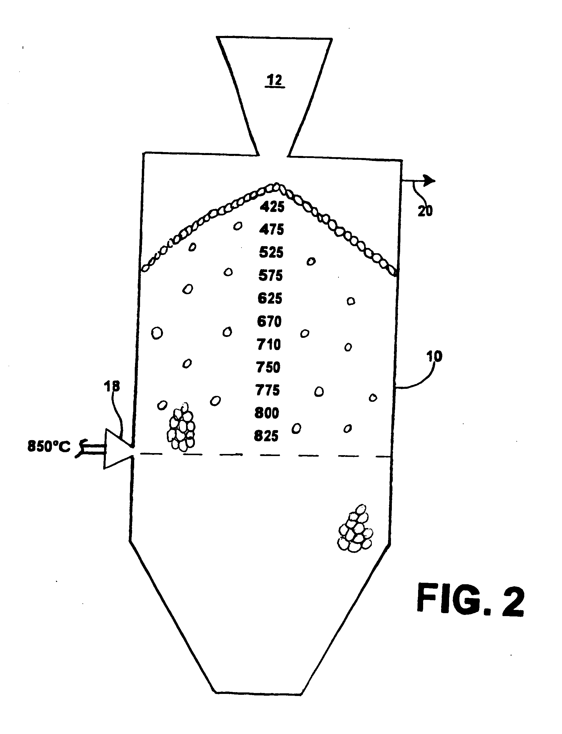
[0018] As shown in FIG. 1, a direct reduction furnace 10 has an upper charging end with means 12 for charging lump ore and / or oxide pellets into the furnace to form a burden 14. The lower end 16 of the furnace has a discharge means for discharging the reduced metallized product from the furnace, and causing the burden to move downwardly as the metallized product is removed. At the middle of furnace is a reducing gas injection system 18 made up of a bustle and tuyeres. Hot reducing gas is injected into the furnace through the bustle and tuyeres.

[0019] Reacted reducing gas, or spent off-gas, principally carbon dioxide and steam, is removed from top of the furnace at 20, cleaned, and passed through a reformer 22 to change it to reducing gas, principally hydrogen and carbon monoxide, for reintroduction to the furnace through the bustle and tuyeres. The fuel gas 24 utilized for heating the reformer is combusted and results in a hot waste off-gas 25 from which heat is usually recovered. ...


PUM

PropertyMeasurementUnit
Timeaaaaaaaaaa
Electric chargeaaaaaaaaaa

Abstract

An improved method and apparatus for pretreatment of solid lump feed material for gas and pellet/lump-based direct reduction processes, by initially storing the lump feed in stockpiles for stress release, followed by pre-drying the feed material prior to charging into the reduction furnace and finally increasing the average temperature of the reduction furnace, in order to reduce the amount of reduction at low temperatures, thereby minimizing the formation of fines within the furnace.

Description

CROSS REFERENCE TO RELATED APPLICATION [0001] This application claims the benefit of U.S. Provisional Application No. 60 / 450,855, filed Feb. 28, 2003.FIELD OF THE INVENTION [0002] The present invention relates to a method and apparatus for pre-treatment of solid lump feed material for gas and pellet / lump-based moving bed direct reduction processes, and more particularly to a method and apparatus for storing and pre-drying the solid lump feed prior to charging in the direct reduction furnace, followed by raising the effective reducing temperature throughout the moving bed. BACKGROUND OF THE INVENTION [0003] In a shaft furnace reduction process, iron ore or iron oxide in lump or pelletized form is fed into the upper portion of the furnace to form a burden of such lumps and / or pellets. Reducing gas is introduced into the mid-portion of the shaft furnace, usually about the periphery, through a bustle and tuyere arrangement. The reducing gas introduction temperature is generally about 85...

Claims


Application Information

Patent Timeline
IPC IPC(8): C21B13/14C22B1/00C22B5/12
CPCC21B13/02C21B13/14C22B5/12C21B2100/04C22B1/00C21B2100/02C21B2100/44C21B2100/66C21B2100/22C21B2100/26Y02P10/134Y02P10/25
Inventor POTTER, STEPHEN M.QUARIGUASI NETTO, PEDRO GUTEMBERG
Owner VALE LIMITED
Why Eureka
Try Eureka