

Apparatus for forming a three-dimensional product
a three-dimensional product and apparatus technology, applied in the direction of additive manufacturing processes, applications, manufacturing tools, etc., can solve the problems of difficult to draw with certainty a desired pattern, step requires labor and time, and time and cost, and achieve the effect of enhancing the strength of the three-dimensional produ
- Summary
- Abstract
- Description
- Claims
- Application Information
AI Technical Summary
Benefits of technology
Problems solved by technology
Method used
Image

Examples
first embodiment
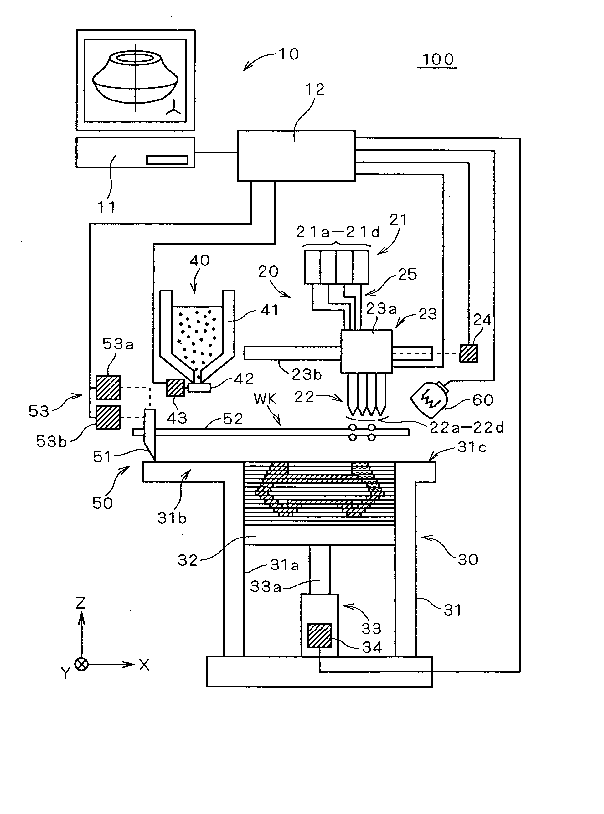
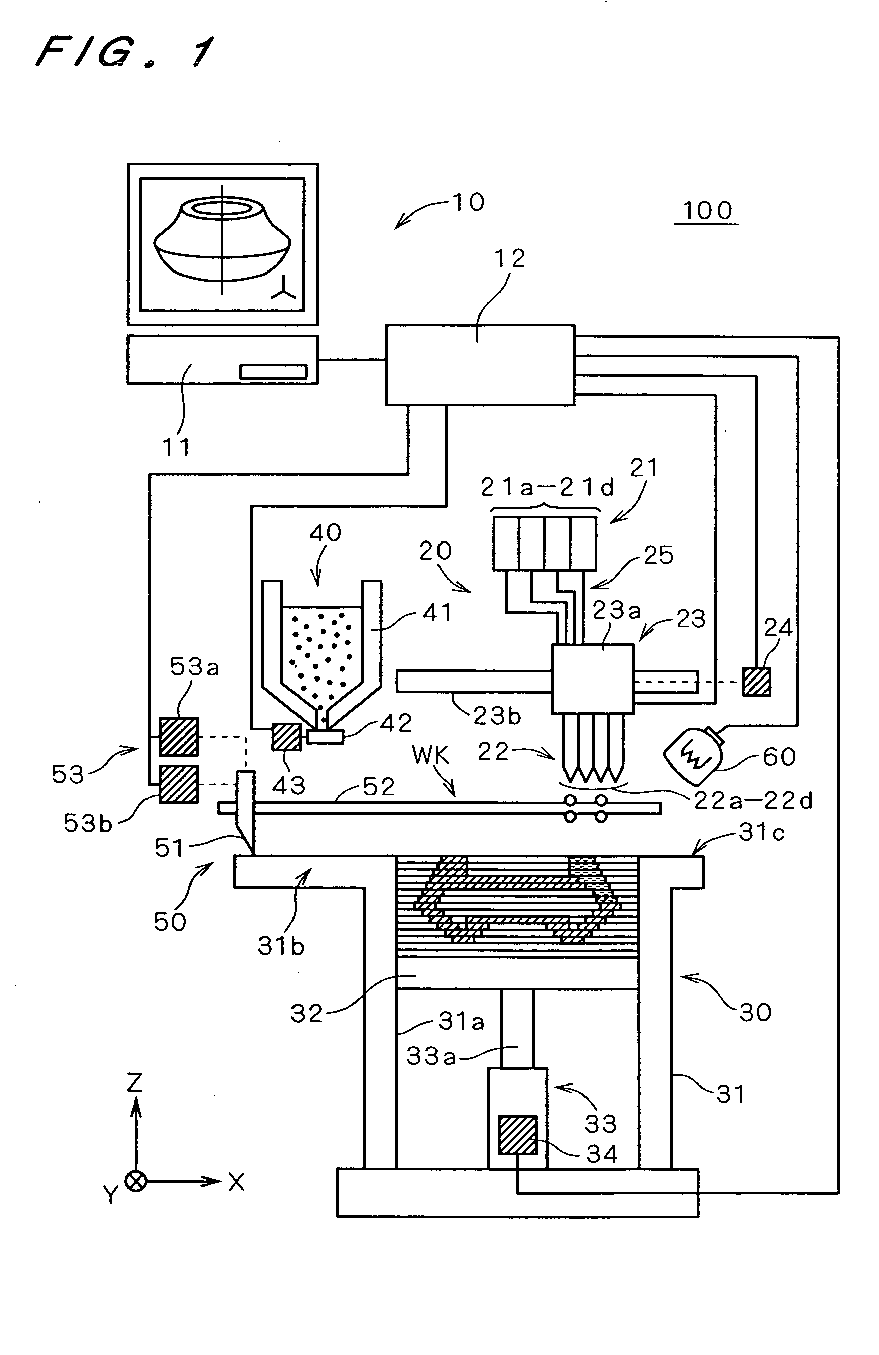
1-1. Construction of Principal Part of 3D Product Forming Apparatus FIG. 1 is a schematic view showing a 3D product forming apparatus 100 according to the Here, in FIG. 1, XYZ directions determined for the sake of explanation are shown with arrows.
The 3D product forming apparatus 100 comprises a controlling part 10 as well as a binder applying part 20, a product forming part 30, a powder supplying part 40, a powder spreading part 50, and an infrared lamp 60, which are electrically connected with the controlling part 10, respectively.
The controlling part 10 includes a computer 11 and a drive controlling part 12 electrically connected with the computer 11.
The computer 11 is a general desk-top type computer or the like which is constructed to include a CPU, a memory, and others in the inside thereof. This computer 11 turns the 3D shape of an original object into data as model data, and outputs cross-section data, which is obtained by slicing the product into thin cross-section bo...
third embodiment
FIG. 13 is a schematic view showing a 3D product forming apparatus 100B according to the Two blades 51Ba and 51Bb are disposed on both sides of the XY-direction moving part 23B. The left blade 51Ba and the right blade 51Bb are mirror-symmetric with respect to the YZ-plane.
The driving part 24B for driving the XY-direction moving part 23B serves to drive the above-mentioned two blades independently in the up-and-down direction (Z-direction). On the basis of instructions from the drive controlling part 12, the movement of the nozzle head 22 in the XY-plane and the ascending and descending movement of the blades 51Ba and 51Bb in the up-and-down direction are made possible. Here, with respect to the movement of the XY-direction moving part 23B, the right direction of the paper sheet (the direction of increasing X) is referred to as the forward direction, and the left direction of the paper sheet (the direction of decreasing X) is referred to as the backward direction.
Further, the 3D ...
fourth embodiment
As described above, in the 3D product forming apparatus 100C a 3D product in which the color and the configuration thereof are suitably reproduced can be formed quickly by applying the ink, which is a material that requires a shorter period of time for stabilization after being applied to the powder layer, before the binders are applied.
5. Fifth Preferred Embodiment
In the above-mentioned embodiments, a material having a different color is supplied from each nozzle. However, it is possible to adopt a construction in which plural kinds of materials (binding agents) that each provide a different sense of mass (including feel of surface and hardness) of the product are jetted from the respective nozzles irrespective of the colors.
Among these, examples of a plurality of binding agents having different senses of mass are: (1) a combination of a binder having a luster and a binder having no luster, (2) a combination of a binder visually having a particulate property and a binder th...
PUM
| Property | Measurement | Unit |
|---|---|---|
| Mass | aaaaa | aaaaa |
| Color | aaaaa | aaaaa |
| Area | aaaaa | aaaaa |
Abstract
Description
Claims
Application Information