Laser driver circuit with reduced noise and optical pickup circuit for use with the same

a laser driver and circuit technology, applied in the field of amplifier circuits, can solve the problems of emi (electromagnetic interference) noise, adverse effects of optical pickup playback signal, reflected beam from optical disc, etc., and achieve the effect of reducing emi noise and siz

Inactive Publication Date: 2005-01-06
ROHM CO LTD
View PDF5 Cites 11 Cited by
  • Summary
  • Abstract
  • Description
  • Claims
  • Application Information

AI Technical Summary

Benefits of technology

[0006] The inventor developed the present invention in view of the aforementioned problems. It is therefore

Problems solved by technology

The optical return noise caused by a reflected beam from the optical disc may have adverse effects on an optical pickup playback signal.
On the other hand, superposing a high-frequency current on the drive current for the laser emis

Method used


Image

  • Laser driver circuit with reduced noise and optical pickup circuit for use with the same
  • Laser driver circuit with reduced noise and optical pickup circuit for use with the same
  • Laser driver circuit with reduced noise and optical pickup circuit for use with the same

Examples


first embodiment

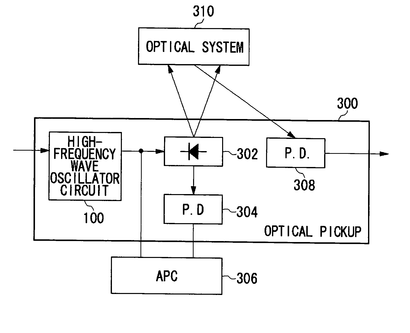
[0024] A first embodiment of the present invention provides an optical disc apparatus which includes a pair of a laser emission element and an optical sensor element. The pair of the laser emission element and the optical sensor element is provided within an optical pickup circuit, while a drive element for driving the laser emission element is incorporated into a laser driver circuit to be accommodated within the optical pickup circuit.

[0025]FIG. 7 illustrates the configuration of an optical disc apparatus according to the first embodiment of the present invention. The optical disc apparatus 60 includes a main circuit board 61 and an optical pickup circuit 62. The main circuit board 61 mainly includes an APC circuit 65. The optical pickup circuit 62 mainly includes a laser emission element LD, an optical sensor element PD, and a laser driver circuit 63. The laser emission element LD is a semiconductor laser diode which emits light when a current is applied thereto. The laser emiss...

second embodiment

[0029] An optical disc apparatus according to this embodiment is different from the first embodiment of the present invention in having a plurality of laser emission elements, optical sensor elements, APC circuits, and transistors serving as drive elements. In particular, this embodiment has circuits or elements in twos such as laser emission elements, each for use with CDs and DVDs. Now, this embodiment will be explained below with a particular emphasis on the difference from the first embodiment of the present invention.

[0030]FIG. 8 shows the configuration of an optical disc apparatus according to the second embodiment of the present invention. A main circuit board 61 mainly includes a first APC circuit 75 and a second APC circuit 76. An optical pickup circuit 62 mainly includes a first laser emission element LD1, a second laser emission element LD2, a first optical sensor element PD1, a second optical sensor element PD2, and a laser driver circuit 63. The first and second laser ...

fifth embodiments

THIRD TO FIFTH EMBODIMENTS

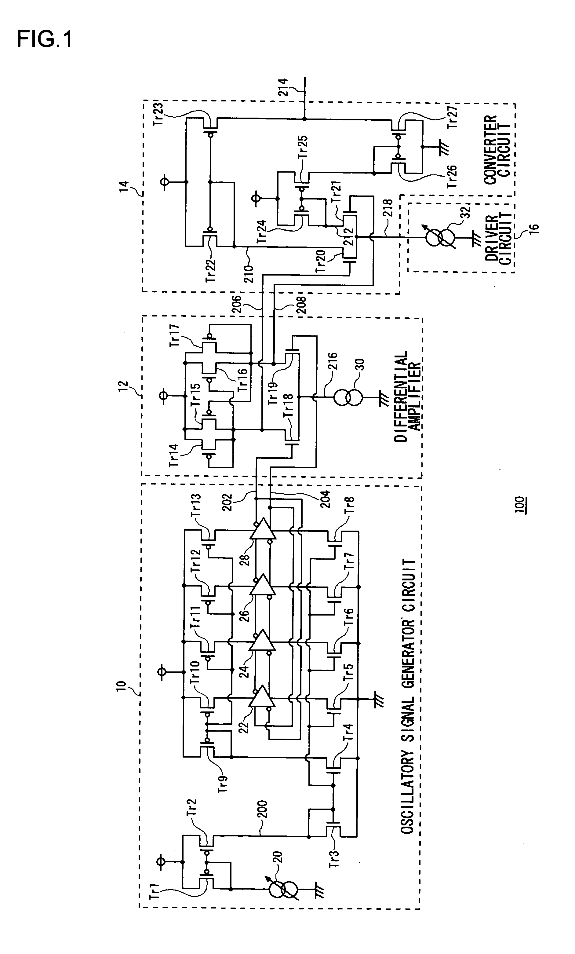
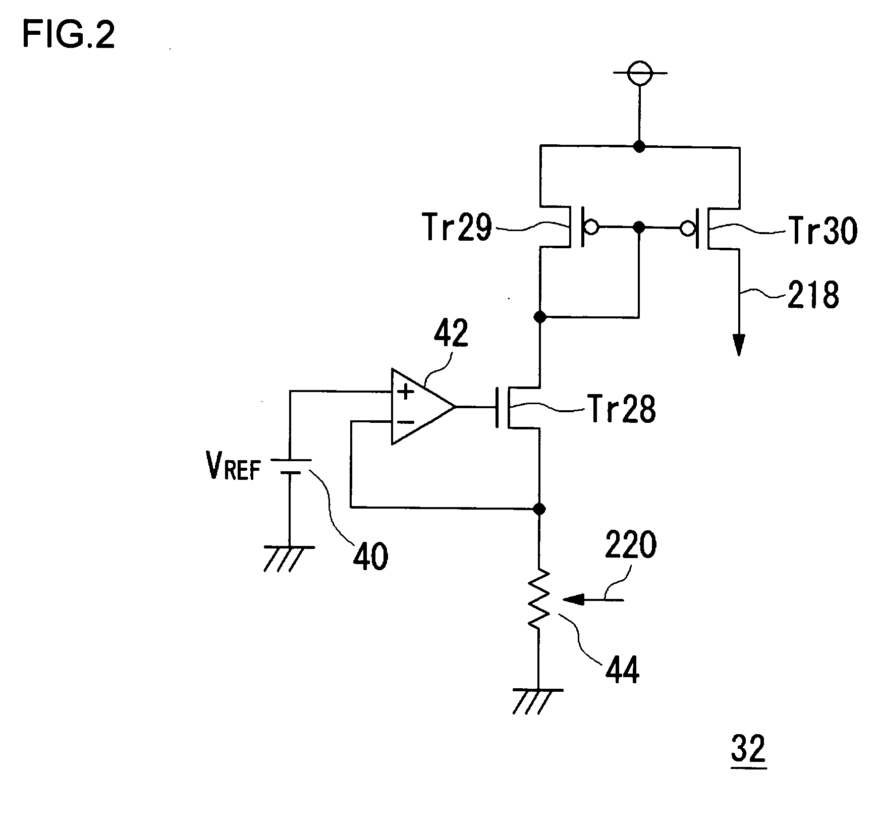
[0035] The high-frequency wave superposition circuit 64 and the optical pickup circuit 62 according to the first and second embodiments of the present invention may also be practiced as in the third through fifth embodiments discussed below.

PRECONDITIONS FOR THIRD TO FIFTH EMBODIMENTS

[0036] For example, the conventional voltage controlled oscillator circuit is used for an optical pickup or PLL (Phase Locked Loop), and generally varies an oscillation frequency setting in accordance with an applied control voltage to provide an oscillatory output signal at the oscillation frequency. An example of the conventional voltage controlled oscillator has an inverting amplifier, a first charge / discharge circuit, and a second charge / discharge circuit, which are connected in that order with the last connected back to the first. In this configuration, the phase of an inverted voltage signal from the inverting amplifier is delayed in a stepwise manner in the first and s...


PUM


Abstract

An optical pickup with a laser driver circuit is provided to overcome an increase in size of an optical pickup, which is caused by a ferrite bead or capacitor being provided in a drive current path to reduce EMI noise effects. In an optical disc apparatus, an optical sensor element detects a laser beam from a laser emission element included in an optical pickup circuit and then sends the detected signal to a main circuit board. An APC circuit in the main circuit board outputs a control signal to control the laser output from the laser emission element at a constant level in accordance with the detected signal from the optical sensor element. A laser driver circuit included in the optical pickup circuit incorporates a transistor and a high-frequency wave superposition circuit). The transistor produces a drive current in accordance with the control signal from the APC circuit, while the high-frequency wave superposition circuit superposes a high-frequency current on the drive current. The drive current superposed with the high-frequency current drives the laser emission element.

Description

BACKGROUND OF THE INVENTION [0001] 1. Field of the Invention [0002] The present invention relates to amplifier circuits, and more particularly, to a technique for improving the frequency characteristics of a differential amplifier circuit. [0003] 2. Description of the Related Art [0004] Conventionally, a method for reducing optical return noise generated in an optical pickup, such as a CD or DVD drive apparatus, is known in which a high-frequency wave superposition module is used (e.g., see Japanese Patent Laid-Open Publication No. Hei 5-48184). In general, the optical pickup employs a laser emission element to read information on optical discs such as CDs or DVDs. The optical return noise caused by a reflected beam from the optical disc may have adverse effects on an optical pickup playback signal. To overcome this problem, the high-frequency wave superposition module is designed to superpose a high-frequency current on the drive current for the laser emission element to stabilize ...

Claims


Application Information

Patent Timeline
IPC IPC(8): G11B7/125G11B7/00G11B7/085G11B7/12G11B7/1263H01L29/00H01S5/062H01S5/0683H03F3/08
CPCG11B7/1263H03F3/08H01S5/0683G11B7/126H01S5/062
Inventor MARUYAMA, SHO
Owner ROHM CO LTD
Why Eureka
Try Eureka