Method of forming a carbon nano-material layer using a cyclic deposition technique

a carbon nano-material and cyclic deposition technology, applied in the direction of polycrystalline material growth, crystal growth process, coating, etc., can solve the problems of shortcomings of the above methods

Active Publication Date: 2005-01-06
SAMSUNG ELECTRONICS CO LTD
View PDF8 Cites 233 Cited by
  • Summary
  • Abstract
  • Description
  • Claims
  • Application Information

AI Technical Summary

Benefits of technology

[0016] The source gas and / or the first reactant gas may be excited by using plasma or light during the injection of the source gas and the first reactant gas. Thus, the CVD layer may be easily formed. Further, the second reactant gas may be excited by using plasma or light during the injection of the second reactant gas. Thus, impurities may be easily removed from the CVD layer.

Problems solved by technology

However, the above methods are not without shortcomings.
For example, conventional forming techniques may tend to involve relatively high substrate temperatures, generate carbon particles by gas phase reaction, and / or suffer from carbon particles interfering with the formation of a carbon nano-material layer having a desired shape and property.

Method used


Image

  • Method of forming a carbon nano-material layer using a cyclic deposition technique
  • Method of forming a carbon nano-material layer using a cyclic deposition technique
  • Method of forming a carbon nano-material layer using a cyclic deposition technique

Examples


Embodiment Construction

[0026] Reference will now be made to exemplary, non-limiting embodiments of the present invention, which are illustrated in the accompanying drawings. It will be appreciated that the present invention is not limited by any of the details of the exemplary embodiments explained herein, but instead may be embodied in numerous and varied forms. The exemplary embodiments of the present invention are provided merely to thoroughly completely convey ideas of the present invention to those skilled in the art. The drawings are not drawn to scale. For example, a thickness of the illustrated layers may be exaggerated to improve clarity. In the drawing, same reference numerals are used for the same elements.

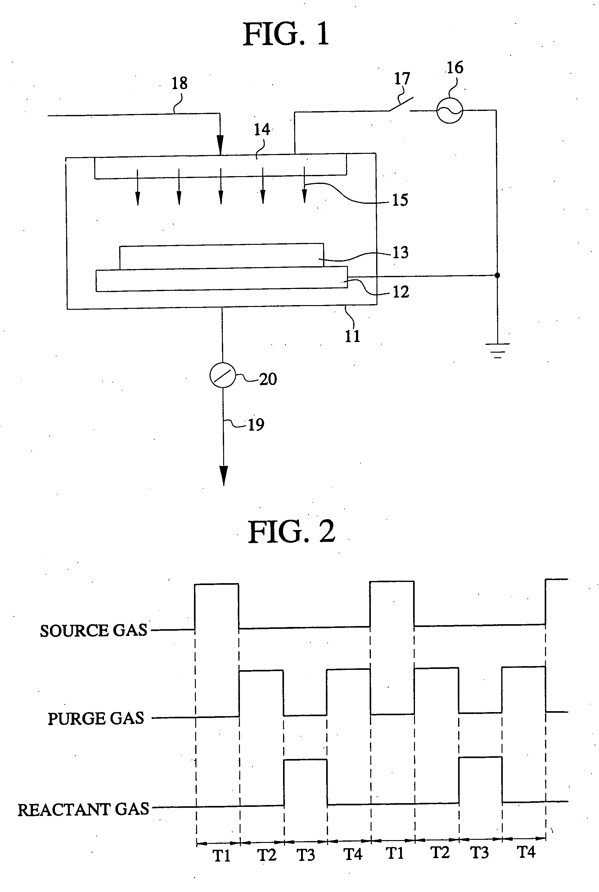
[0027]FIG. 1 schematically shows a typical cyclic deposition apparatus using a direct plasma. This apparatus may be used to implement embodiments of the present invention. As shown, a reactor 11 may contain a susceptor 12. The susceptor may support a substrate 13 and transfer heat to maintai...


PUM

PropertyMeasurementUnit
temperatureaaaaaaaaaa
timeaaaaaaaaaa
timeaaaaaaaaaa

Abstract

A method of forming a carbon nano-material layer may involve a cyclic deposition technique. In the method, a chemisorption layer or a chemical vapor deposition layer may be formed on a substrate. Impurities may be removed from the chemisorption layer or the chemical vapor deposition layer to form a carbon atoms layer on the substrate. More than one carbon atoms layer may be formed by repeating the method.

Description

[0001] This application claims priority under 35 U.S.C. §119 to Korean Patent Application Nos. 2003-0045447 and 2004-0021824, filed on Jul. 4, 2003 and on Mar. 30, 2004, respectively, the contents of which are incorporated by reference in their entirety. BACKGROUND OF INVENTION [0002] 1. Field of the Invention [0003] The present invention relates in general to a method of forming a carbon nano-material layer, and more particularly, to a method of forming a carbon nano-material layer using a cyclic deposition technique. [0004] 2. Description of Related Art [0005] Carbon may have four types of crystal structures such as diamond, graphite, fullerene, and carbon nanotube (CNT). Fullerene and CNT may be considered as carbon nano-materials. Fullerene may be composed of sixty carbon atoms and may be a 64-hedron with a soccer ball shape. CNT may be formed into hexagonal honeycomb structures wound into a tube shape, in which there are several types of shapes such as a single wall shape, a mu...

Claims


Application Information

Patent Timeline
Patent Type & Authority Applications(United States)
IPC IPC(8): C23C16/00C23C16/02C23C16/26C23C16/44C23C16/455C30B29/02C30B29/60
CPCC23C16/0281C23C16/26C30B29/605C30B29/02C23C16/4554
Inventor WON, SEOK-JUNKWON, DAE-JINJEONG, YONG-KUK
Owner SAMSUNG ELECTRONICS CO LTD
Why Eureka
Try Eureka