
Apparatus and method for concurrently monitoring active release and physical appearance of solid dosage form pharmaceuticals

a technology of active release and monitoring apparatus, applied in chemical methods analysis, instruments, suspensions and porous materials analysis, etc., can solve the problems of uneven stirring of dissolution liquid, uneven equipment, and non-uniform dissolution liquid in the chamber, and achieve high quality

Inactive Publication Date: 2005-01-06
ALKERMES PHARMA IRELAND LTD
View PDF9 Cites 26 Cited by
  • Summary
  • Abstract
  • Description
  • Claims
  • Application Information

AI Technical Summary

Benefits of technology

The patent describes an apparatus and method for monitoring the dissolution properties of solid dosage form pharmaceuticals or other agents. The method involves placing the dosage form in a chamber and adding a dissolution liquid to watch it dissolve. The dissolution liquid is analyzed as the dosage form dissolves to determine its properties. The apparatus includes a chamber with a support for the dosage form and a video monitoring system to capture images of the dosage form as it dissolves. The invention allows for controlled temperature of the dissolution liquid and simultaneous monitoring of the dosage form and its dissolution liquid.

Problems solved by technology

While USP I apparatus may be generally suitable for their purposes, they nevertheless suffer from various significant disadvantages.
One of the most significant disadvantages is the non-uniformity of the dissolution liquid in the chamber due to the production of poor eddy currents or inadequate stirring.
In addition, the baskets of USP I equipment are relative fragile and can be bent or otherwise deformed, whereupon their rotation in a bent or deformed state-may result in uneven stirring of the dissolution liquid.
Another significant disadvantage of this USP I equipment is that the baskets may become clogged, thereby impeding the access of the dissolution liquid to the dosage form.
Lastly, USP I apparatus is not particularly suitable for testing the dissolution of a solid dosage form under changing pH conditions, e.g., conditions where pH increases, such as occurs when the dosage form is taken orally by a patient.
While USP II apparatus may also be generally suitable for their purposes they also suffer from various drawbacks.
One drawback is the non-uniformity of the dissolution liquid in the chamber due to the creation of a conical “blind-spot” of less concentrated dissolution liquid directly under the paddle.
Another drawback is that the dosage form is susceptible to floating, if not held in position by a helix or lobster pot, thereby interfering with its even dissolution.
Moreover, since the dosage form is exposed, it can be struck by the paddle, possibly breaking the dosage form and thus interfering with its normal dissolution properties.
Further still the dosage form may rest on or stick to the inner surface of the chamber, thereby reducing the surface area of the dosage form so that an accurate reading of its dissolution properties is compromised.
The use of a helix, lobster pot or other device to surround the dosage form to lift it off the surface of the chamber may eliminate that problem, but is not conducive for use with dosage formulations that swell, e.g., hydrogels.
Moreover, like USP I apparatus, USP II apparatus is not particularly suitable for testing the dissolution of a solid dosage form under changing pH conditions
Moreover, the apparatus is difficult to use with a surfactant based dissolution liquid, as frothing of the liquid severely limits the sample holder reciprocation rate.
Further still, clogging of the sample holder mesh is possible, thus obstructing the free flow of dissolution liquid past the sample formulation.
Notwithstanding these advantages, USP IV equipment still suffers from its own disadvantages, e.g., it requires large volumes of dissolution liquid, calibration tests are unavailable, and validation of the flow rate is difficult.
While USP V equipment offers advantage over USP II equipment for transdermal dosage forms, it never the less suffers from the same disadvantages of that equipment insofar as the non-uniformity of the dissolution liquid in the chamber is concerned.
While all of the above identified apparatus and methods of use may be suitable for their intended purposes they still leave much to be desired from the standpoint that the information about the dissolution properties of the solid dosage forms that can be determined by their use is somewhat limited.
In this regard prior art apparatus and techniques may enable one to determine the rate at which a particular solid dosage form dissolves (i.e., its so-called “dissolution profile”), but they do not provide accurate information about the mechanism of how the dosage form actually dissolved, e.g., by erosion, disintegration, diffusion and / or combinations of those actions.
Moreover, while some prior art dissolution testing systems may have included utilizing a visualization device, e.g., a camera to record selected images of the dosage forms during their process of dissolving, such techniques have been very limited in the quality of the images provided, particularly where the dosage forms are susceptible to movement and displacement in the apparatus as they dissolve.
For example, as is known the rotating paddles of USP II devices tend to cause the dosage forms to shift around and move in the dissolution vessel, thereby making sustained, accurate imaging difficult.
Moreover, the stirring of the dissolution liquid causes surface turbulence, rendering image acquisition through the surface difficult.
The rotating basket of USP I apparatus also presents an imaging problem since the basket in which the dosage form is located is moving and a relatively high speed, thereby tending to blur or otherwise obscure the dosage form during the dissolution process.

Method used


Image

  • Apparatus and method for concurrently monitoring active release and physical appearance of solid dosage form pharmaceuticals
  • Apparatus and method for concurrently monitoring active release and physical appearance of solid dosage form pharmaceuticals
  • Apparatus and method for concurrently monitoring active release and physical appearance of solid dosage form pharmaceuticals

Examples


Embodiment Construction

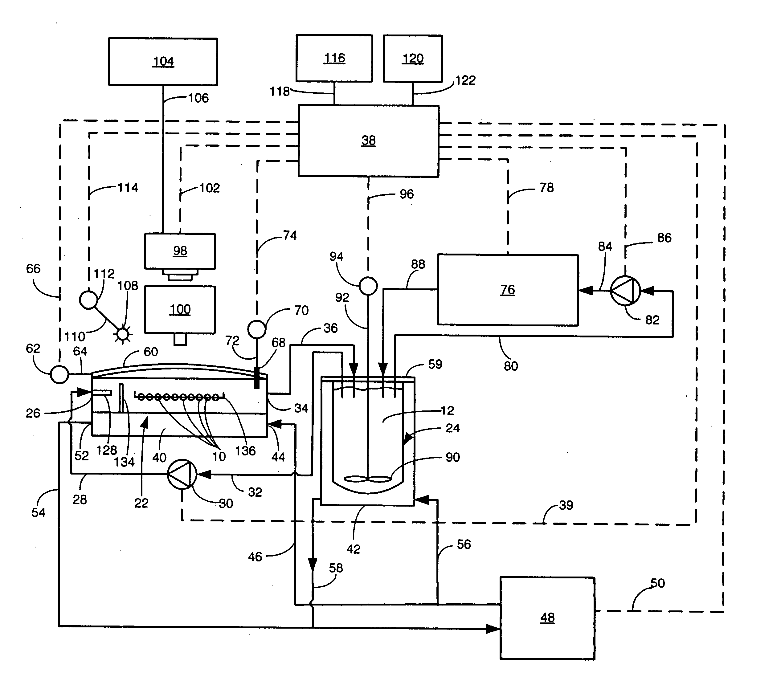
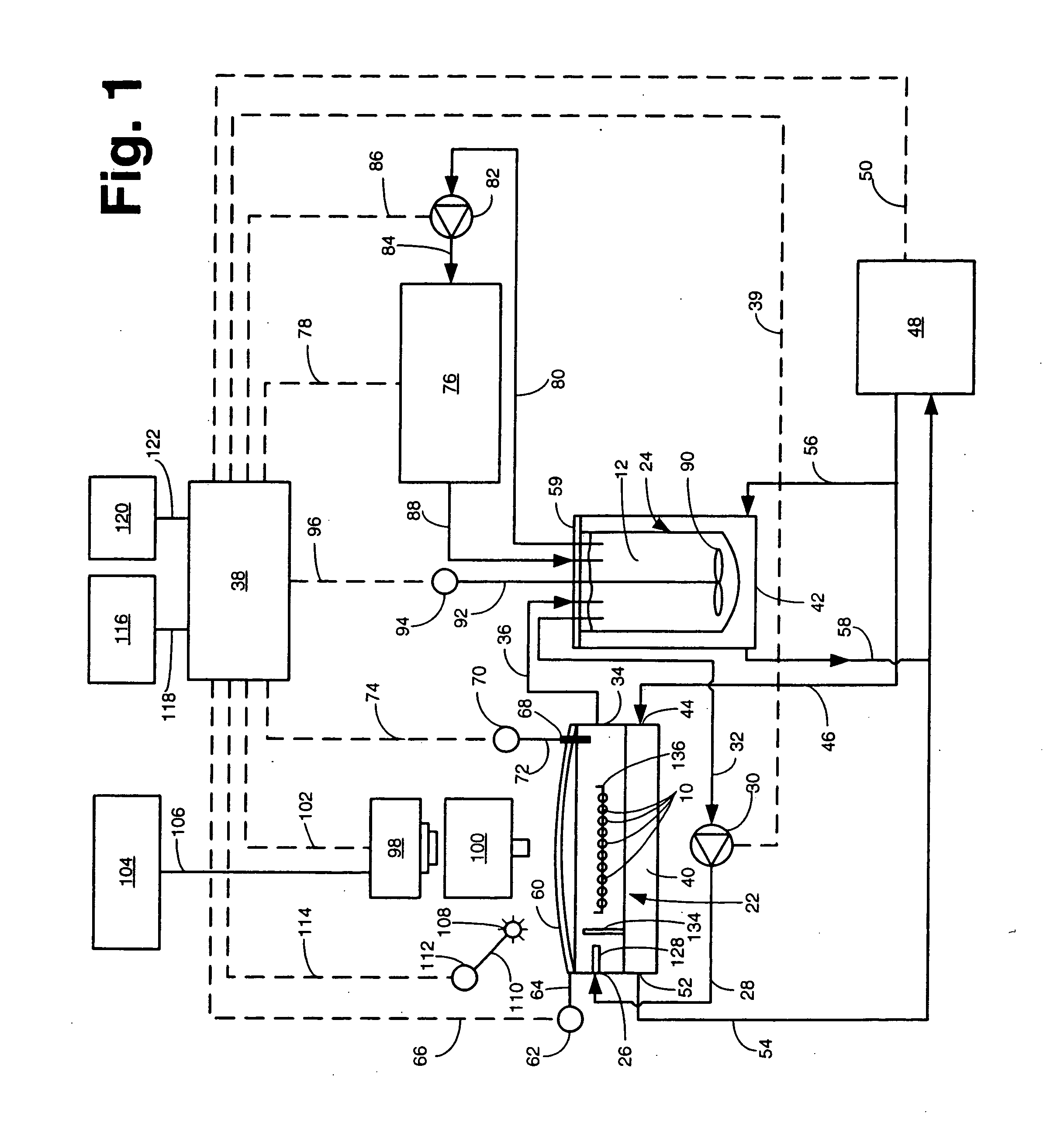
[0030] Referring now to the various figures of the drawing wherein like reference characters refer to like parts, there is shown in FIG. 1 one exemplary embodiment of a system 20 for concurrently monitoring active release and physical appearance of solid dosage form pharmaceuticals constructed in accordance with this invention.

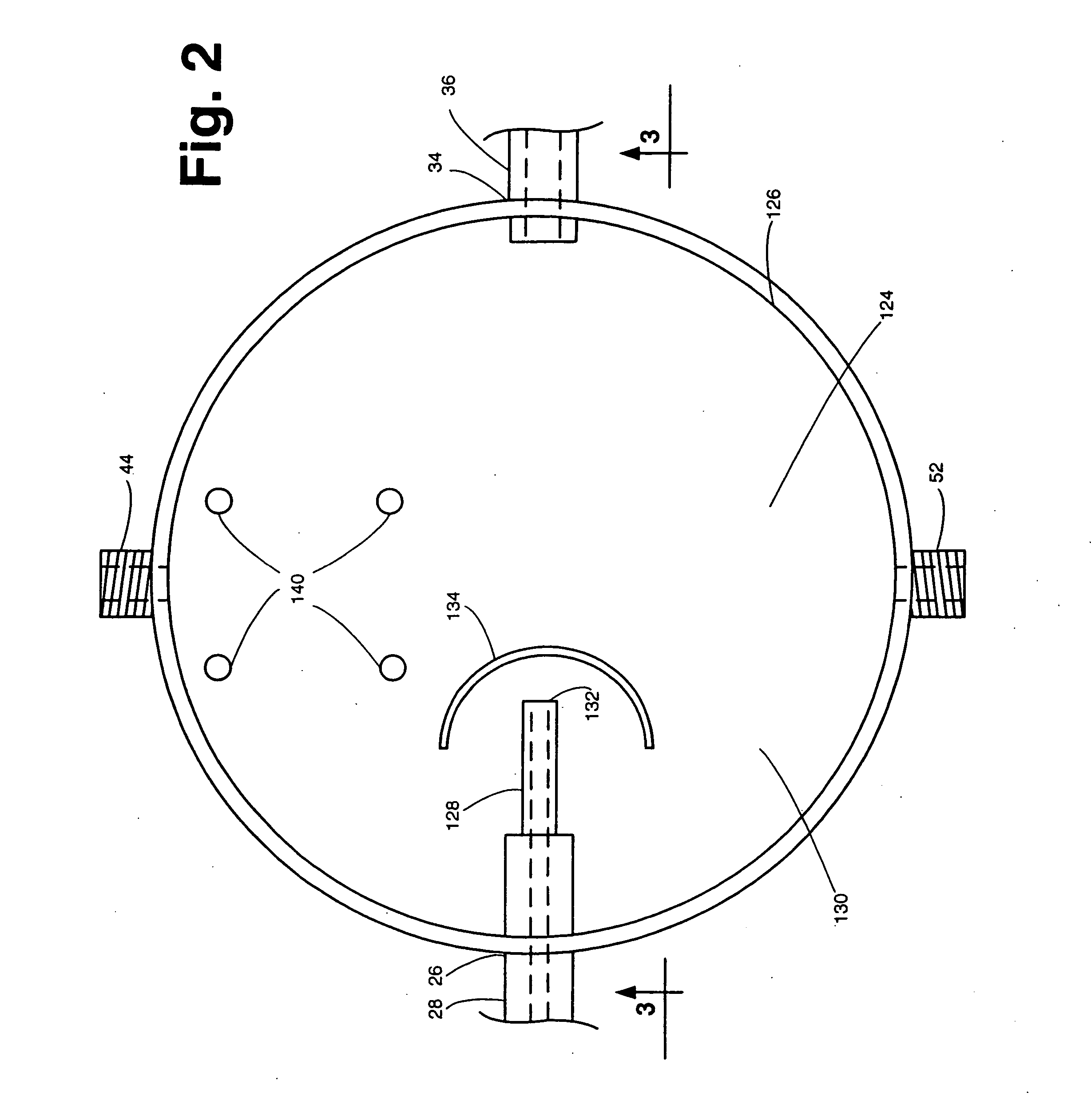
[0031] The system 20 includes a dissolution chamber 22, whose details will be described later with reference to FIGS. 2 and 3, into which at least one, but preferably a plurality of solid dosage form pharmaceuticals 10 are disposed for exposure to a dissolution liquid 12. The dosage forms 10 are located within a predetermined position within the chamber 22 in an area which defines a visualization field (to be described later). The dissolution liquid 12 is provided into the chamber 22 from a dissolution liquid reservoir 24. The details of the reservoir 24 will also be described later. Suffice it for now to state that the reservoir 24 is a hollow member for hol...


PUM

PropertyMeasurementUnit
volumeaaaaaaaaaa
volumeaaaaaaaaaa
pHaaaaaaaaaa

Abstract

An apparatus and method for monitoring the dissolution properties of a solid dosage form pharmaceutical or other material. The apparatus includes a hollow dissolution chamber for supporting the dosage form and subjecting it to a dissolution liquid so that the dosage form dissolves in the liquid. A dissolution liquid analyzing device (e.g., a spectrophotometer) analyzes the properties of the dissolution liquid as the dosage form dissolves. A video monitoring means (e.g., a stereo-microscope and video camera) provides a series of images of the dosage form as it dissolves. The series of images and data resulting from the analysis are recorded and correlated. The temperature, flow rate and chemical parameters of the dissolution liquid can be controlled (e.g., held constant or altered), if desired.

Description

FIELD OF THE INVENTION [0001] This invention relates generally to test apparatus and methods and more particularly to apparatus and methods for testing to determine the dissolution properties of solid dose form pharmaceuticals, agents and other materials. BACKGROUND OF THE INVENTION [0002] It is a well established practice in the pharmaceutical industry to test the dissolution properties of solid dosage form pharmaceuticals. The term solid dosage form as used herein means any dosage form, other than a liquid, and which can be delivered into the body of a being. Examples of such dosage forms are tablets, capsules, caplets, pills, suppositories, transdermal patches, etc. Moreover, the dosage forms may be immediate release or timed release. [0003] As is known, dissolution is the process by which a solid substance dissolves in a solvent and is controlled by the affinity between it and the solvent. The sequence of events in a typical dissolution process entails several actions, e.g., the...

Claims


Application Information

Patent Timeline
Patent Type & Authority Applications(United States)
IPC IPC(8): G01N21/01G01N30/04G01N33/15
CPCG01N33/15
Inventor KYNE, OLIVER
Owner ALKERMES PHARMA IRELAND LTD
Learn More