
Method for hydro-erosive rounding of an edge of a part and use thereof

a technology of hydroerosive rounding and edge, which is applied in the direction of edge grinding machines, grinding machines, manufacturing tools, etc., can solve the problems of reducing efficiency, affecting the accuracy of injection holes, and eccentric injection holes

Inactive Publication Date: 2005-01-06
CONTINENTAL AUTOMOTIVE GMBH
View PDF5 Cites 4 Cited by
  • Summary
  • Abstract
  • Description
  • Claims
  • Application Information

AI Technical Summary

Benefits of technology

[0010] The object of the present invention is to create a method for hydro-erosive rounding of an edge of a part, in particular of an edge in a duct of a high-pressure resistant part, and a use thereof, with which optimum rounding results can be achieved.
[0013] According to the invention, a method for hydro-erosive rounding of an edge of a part, in particular of an edge in a duct of a high-pressure resistant part, in which a liquid to which abrasive elements are added is directed along the edge to be rounded, means that a high-viscosity liquid is used as a liquid, that fast abrasion times can be achieved and that the risk of elutriations by the liquid in the duct is very small. In a preferred embodiment of the invention the liquid has a viscosity in the range between 10 and 100 mm2 / s, preferably approximately 50 mm2 / s.
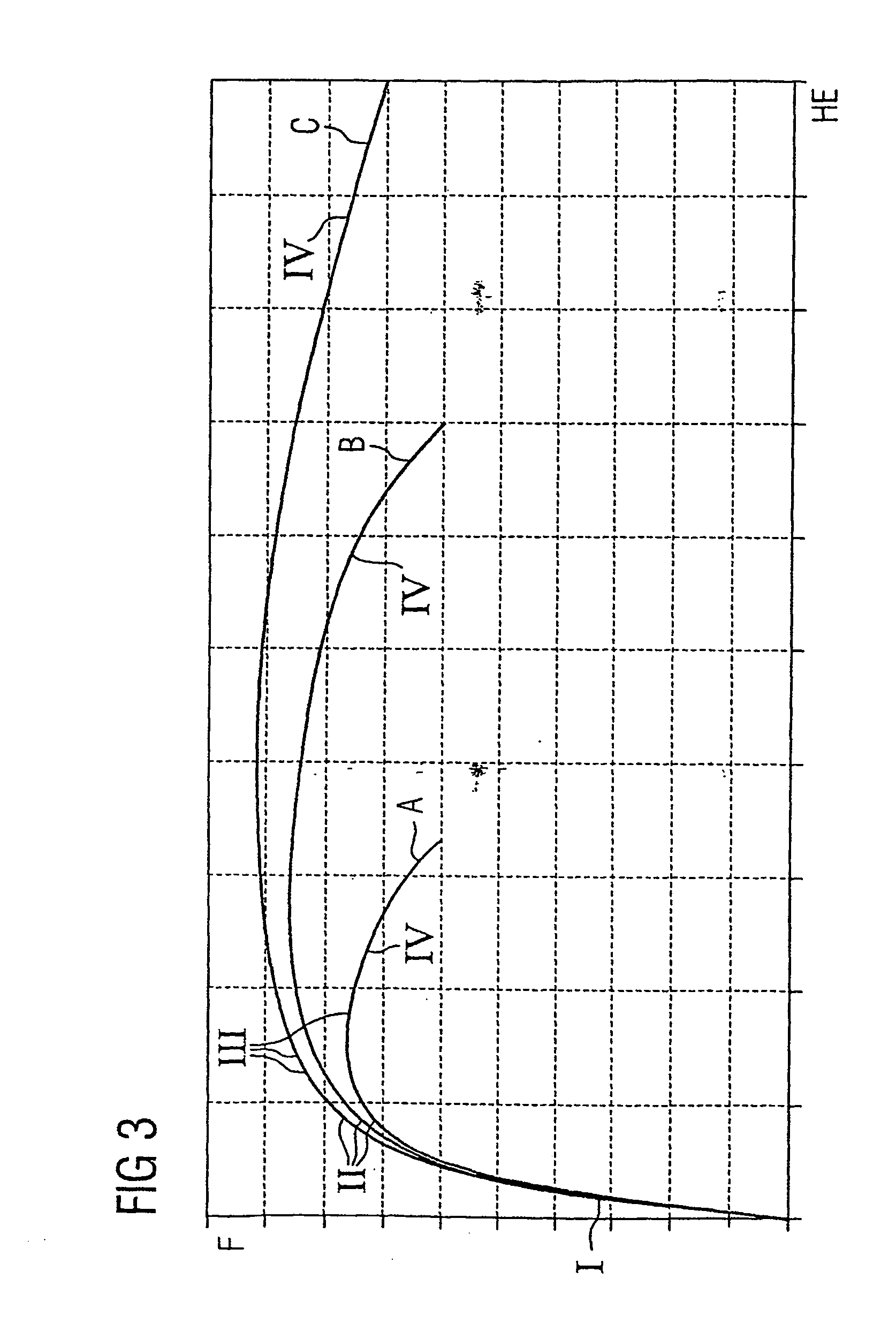
[0014] Advantageously the parts rounded hydro-erosively using the inventive method, in particular injection nozzles for fuels, achieve a high-pressure resistance of over 1800 bar. The oil can also be dissolved in other oils, such as diesel or diesel-like oils, so that after the rounding process the part is easy to clean. Expensive cleaning processes in comparison to the ExtrudeHone method can be dispensed with. After the rounding procedure it is sufficient to flush the part with oil to remove any remaining abrasive elements. Disposal is simpler (no hazardous waste) and the high viscosity ensures a homogeneous distribution of the abrasion particles which is stable over time. These requirements are met by most organic oils. The abrasion times are also considerably reduced, so that cycle times are achieved which enable the rounding method to be used in production processes. Abrasion times can be kept selectively low and the roughness to be achieved can be selectively varied via the supply pressure, the concentration and size of abrasive elements, the viscosity of the abrasion oil and the flow speed of the abrasion oil.
[0017] It is also possible to execute the inventive abrasion method at largely freely selectable abrasion pressures, so that different types of nozzle can be rounded at the wedge using one liquid. For example, low abrasion pressures can be used for parts whose edges are to be only slightly rounded and high abrasion pressures can be used for nozzles which are to be considerably rounded.

Problems solved by technology

Secondly the ageing process occurring in motor operation of the injection nozzle is anticipated, so that in operation this only occurs to a minor extent.
However, a disadvantage of this is that with the standard oil used to date as an abrasive liquid only comparatively small degrees of rounding can be achieved, since when the supply pressure of the abrasive liquid is raised elutriations can be observed as a function of the flow and pressure ratios in the area of the edge to be rounded and these result in an eccentricity of the injection holes and thus in a reduction in efficiency.
The drawback with this is that the flow of the abrasive paste cannot be determined during the abrasion process, which has an adverse effect on adjusting the flow precision of the injection holes.
Residues of this type can result in the injection holes becoming blocked or the nozzle being prevented from being sealed by the nozzle needle.
As a result abrasion times increase phenomenally and the quality achieved still leaves a lot to be desired.
Moreover, in this variant too, the abrasion times are very long and thus not suitable for a production process.
The edge or the wedge is known to be a location at which local peak stresses occur under load which can result in a failure of the injection nozzles.
A high-pressure resistance of above 1600 bar cannot be achieved with electrochemical machining because this process creates a pore-like rough surface resulting in local peak stresses.
However, the problem here is that considerable effort is required to clean the injection nozzle in order to remove the abrasive paste remaining in the injection nozzle after rounding.
There is also a risk that residues of the paste are left in the injection nozzle and the injection holes disposed at the end of the guide bore for the injection nozzle are blocked or the nozzle needle loses its sealing function as a result of the remaining paste.
In such highly stressed parts, peak stresses occur in the area of edges of all kinds, which can result in component failure, in particular rupturing of the component.

Method used


Image

  • Method for hydro-erosive rounding of an edge of a part and use thereof
  • Method for hydro-erosive rounding of an edge of a part and use thereof
  • Method for hydro-erosive rounding of an edge of a part and use thereof

Examples


Embodiment Construction

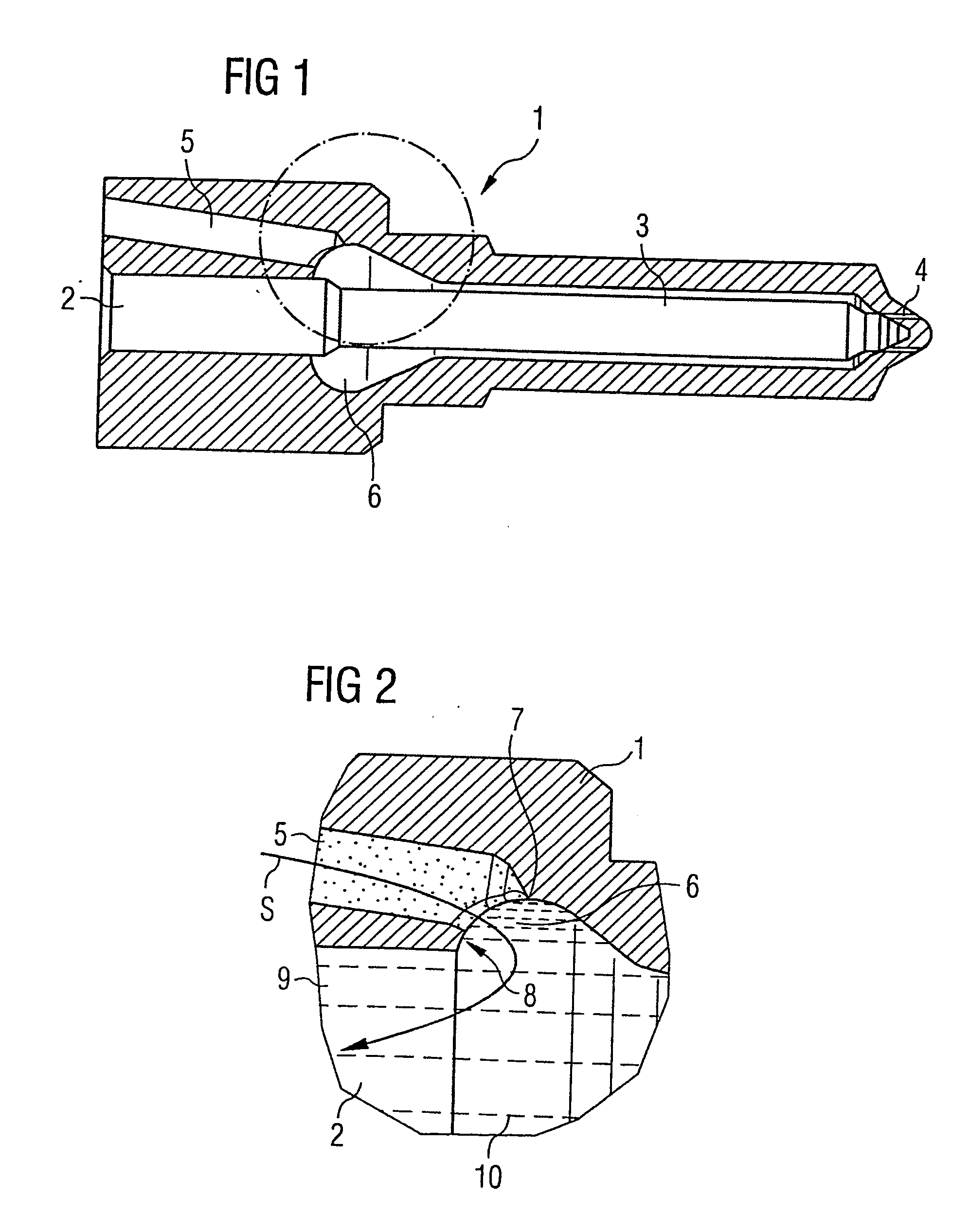
[0022] The inventive method for hydro-erosive rounding of edges in high-pressure resistant parts uses a high-viscosity liquid to which abrasive elements are added. Suitable high-viscosity liquids are abrasion oils with a viscosity in the range between 10 and 100 mm2 / s, preferably approximately 50 mm2 / s. A hydrocarbon oil can be used, for example. The liquid is fed to the edges in the area of high pressure resistant parts via a supply pump (not shown) working at a supply pressure of approximately 10 to 500 bar, preferably 100 bar. By adjusting the supply pressure and the flow speed of the liquid the speed and degree of rounding can be influenced.

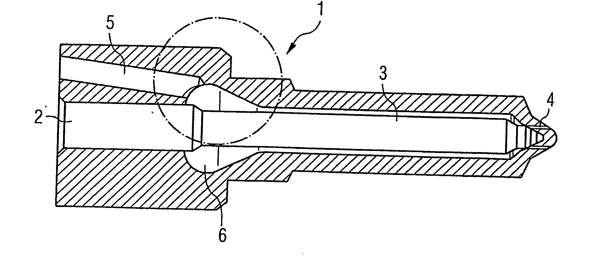
[0023] The inventive rounding method is described below in greater detail in use for an injection nozzle 1 for diesel fuel. FIG. 1 shows a sectional view of a high-pressure resistant injection nozzle 1 for diesel fuel. The overall elongated injection nozzle 1 has a guide bore 2 placed centrally for the nozzle needles 3, which in each case ex...


PUM

PropertyMeasurementUnit
Pressureaaaaaaaaaa
Kinematic viscosityaaaaaaaaaa

Abstract

In a method for the hydro-erosive rounding of an edge of a part, particularly an edge in a duct of a high pressure-resistant part, and a use thereof, a liquid to which abrasive elements are added is directed along the edge that is to be rounded. In order to optimize the result of the rounding process, a high-viscosity liquid is used as a liquid (10). The inventive method is used for rounding parts of a fuel injection system.

Description

CROSS REFERENCE TO RELATED APPLICATION [0001] This application is a continuation of copending International Application No. PCT / DE2003 / 002190 filed Jul. 1, 2003 which designates the United States, and claims priority to German application no. 102 29 897.1 filed Jul. 3, 2002.TECHNICAL FIELD OF THE INVENTION [0002] The present invention relates to a method for the hydro-erosive rounding of an edge of a part, particularly an edge in a duct of a high-pressure resistant part, whereby a liquid to which abrasive elements are added is directed along the edge that is to be rounded. The invention also relates to a use of the said method. DESCRIPTION OF THE RELATED ART [0003] It is generally known that in the case of high-pressure resistant parts, such as for example injection nozzles for diesel fuel, the injection holes for the fuel disposed in the area of a nozzle needle seat of the injection nozzle are eroded into the housing of the injection nozzle. Once the injection holes of the diesel i...

Claims


Application Information

Patent Timeline
IPC IPC(8): B24B1/00B24B31/116B24C1/00
CPCB24B31/116
Inventor FATH, ANDREASFRANK, WILHELM
Owner CONTINENTAL AUTOMOTIVE GMBH
Learn More