

Coating method and planographic printing plate
a technology of coating method and planographic printing plate, which is applied in the direction of lithography, photomechanical equipment, instruments, etc., can solve the problems of increasing equipment costs, and consuming a portion of heat supplied, so as to reduce energy costs and operating costs.
- Summary
- Abstract
- Description
- Claims
- Application Information
AI Technical Summary
Benefits of technology
Problems solved by technology
Method used
Image

Examples
example 1
On a surface of an aluminum web having a thickness of 0.24 mm, after mechanical graining was applied thereto by means of a brush graining method, electrical graining was effected in an alternating current electrolytic bath. Subsequently, anodization was applied so that an amount of an anodization coating be 2 g / m2, followed by rendering hydrophilic, and thereby a support web W was manufactured.
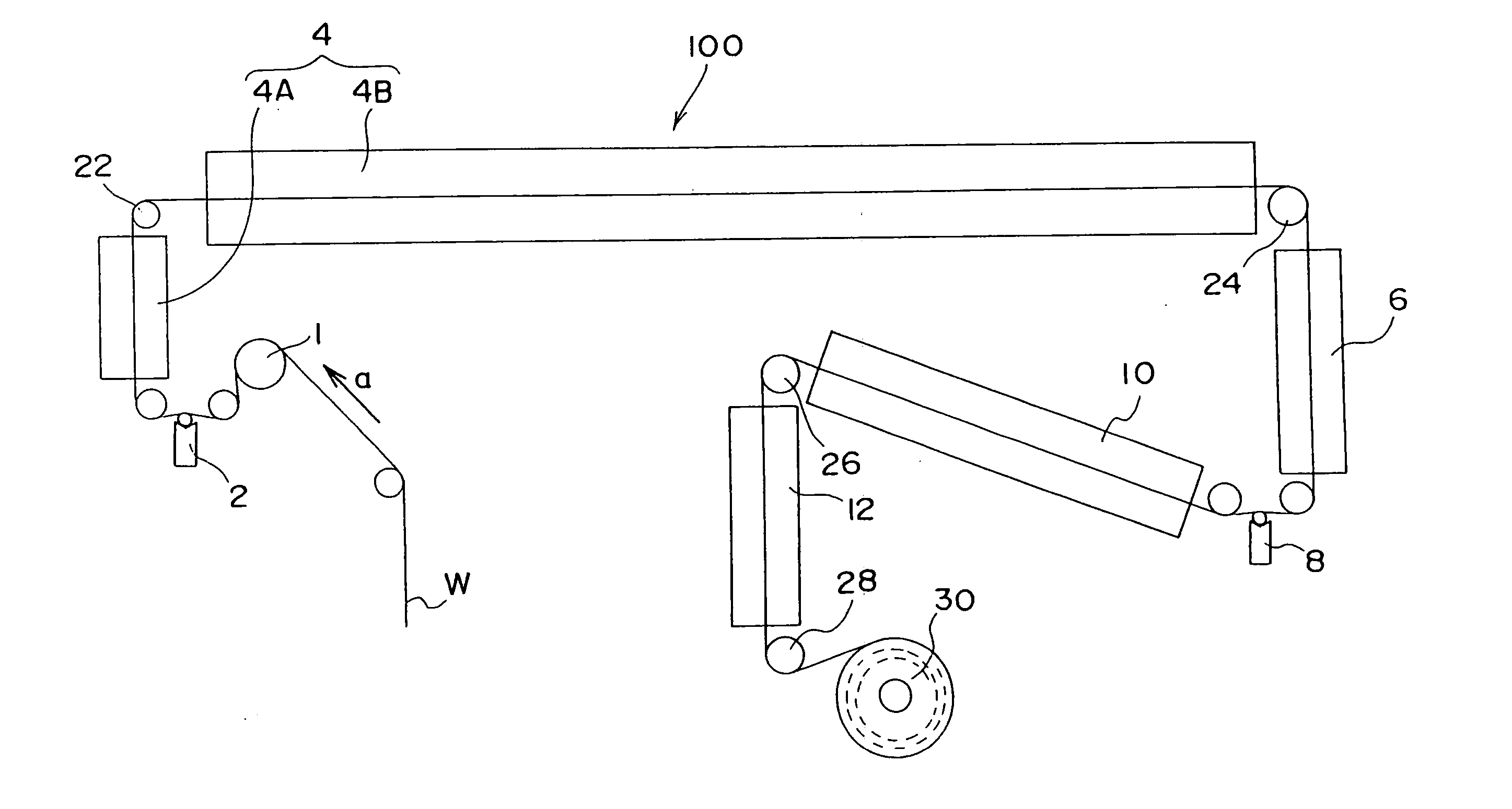
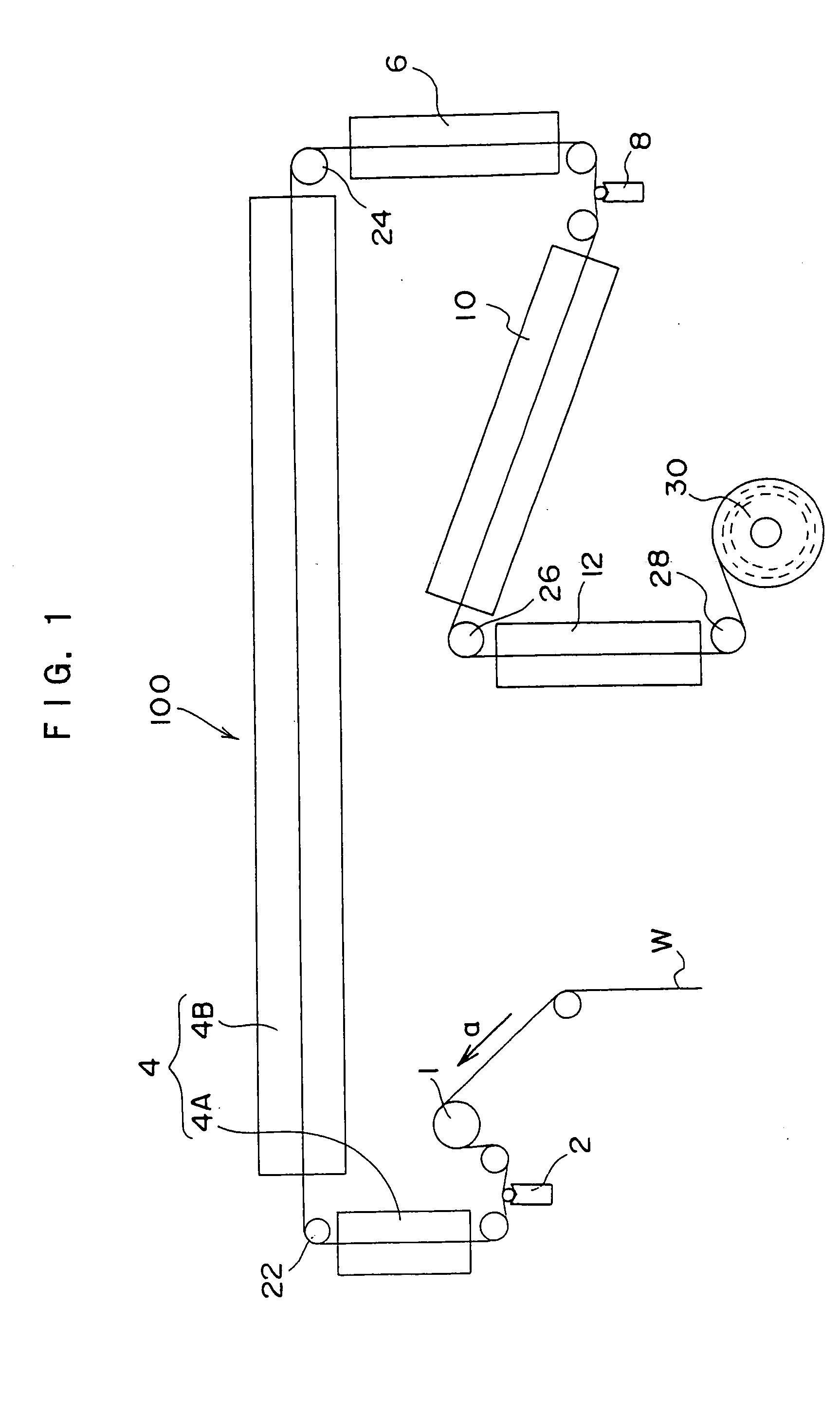
In the next place, by use of the manufacturing line shown in FIG. 1, a photo-polymerizing type laser-sensitive layer forming solution was coated on the roughened surface of the support web W and dried, whereby a photo-polymerizing type laser-sensitive layer was formed. A water-based coating solution was coated thereon to form an intermediate layer. The photo-polymerizing type laser-sensitive layer forming solution was coated so that a dry film weight thereof be 1.5 g / m2 and the water-based coating solution was coated so that a coating weight thereof be 11.3 cc / m2.
A temperature of a drying...
example 2
On a grained surface of a support web manufactured according to the similar procedure as that of Example 1, a photosensitive layer forming solution in which a positive photosensitive resin was blended as a photosensitive resin was coated and dried, by using the manufacturing line shown in FIG. 1. The prescription of the photosensitive layer forming solution is shown below.
(Prescription of Photosensitive Layer Forming Solution)
Ester between 0.9 parts by weight1,2-naphthoquinone-2-diazido-4-sulfonylchloride and m-cresol formaldehyde resin(positive photosensitive resin)Cresol formaldehyde resin 1.9 parts by weight(positive photosensitive resin)Phthalic anhydride 0.2 parts by weight4-[p-N-(p-hydroxybenzoyl)aminophenyl]- 0.02 parts by weight2,6-bis (trichloromethyl)-S-triazineVictoria Pure Blue BOH 0.03 parts by weight(manufactured by Hodogaya Chemical Co., Ltd.)Megafac F-1170.006 parts by weight(fluorinated surfactant, manufactured byDainippon Ink and Chemicals, Incorporated)Methyl...
example 3
On surfaces of five types of aluminum webs each having a thickness of 0.15 mm, 0.20 mm, 0.24 mm, 0.30 mm, and 0.40 mm, the mechanical graining was applied according to the brush graining method, followed by applying the electrical graining in an alternating current electrolytic bath. Subsequently, the anodization was applied thereto so that an amount of an anodization coating was 2 g / m2, followed by rendering the support web W hydrophilic. Support webs W were thus manufactured.
In the next place, by use of the manufacturing line shown in FIG. 1, a photo-polymerizing type laser-sensitive layer forming solution was coated on each of the roughened surfaces of the support webs W and dried, whereby photo-polymerizing type laser-sensitive layers were formed. On each thereof an intermediate layer forming solution was coated to form an intermediate layer.
The photo-polymerizing type laser-sensitive layer forming solution was coated so that an amount of coating solution was 18.8 cc / m2 and...
PUM
| Property | Measurement | Unit |
|---|---|---|
| temperature | aaaaa | aaaaa |
| dew point | aaaaa | aaaaa |
| boiling point | aaaaa | aaaaa |
Abstract
Description
Claims
Application Information