Suck back valve

a back valve and valve body technology, applied in the field of back valves, can solve the problems of unnecessary piping operation, and achieve the effects of reducing installation space, light weight, and small siz

Active Publication Date: 2005-01-13
SMC CORP
View PDF19 Cites 44 Cited by
  • Summary
  • Abstract
  • Description
  • Claims
  • Application Information

AI Technical Summary

Benefits of technology

[0013] A general object of the present invention is to provide a suck back valve which reduces the installation space by realizing a small size and a light weight and which eliminates any piping operation with respect to an ON / OFF valve.

Problems solved by technology

Further, it is unnecessary to perform any piping operation with respect to the ON / OFF valve unlike the conventional technique.

Method used


Image

  • Suck back valve
  • Suck back valve
  • Suck back valve

Examples


Embodiment Construction

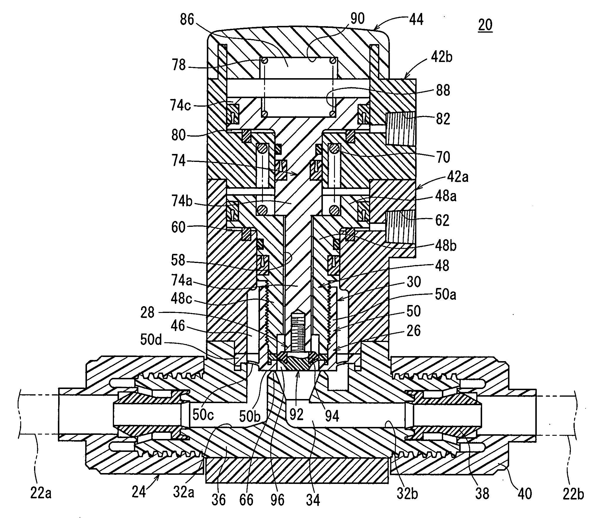
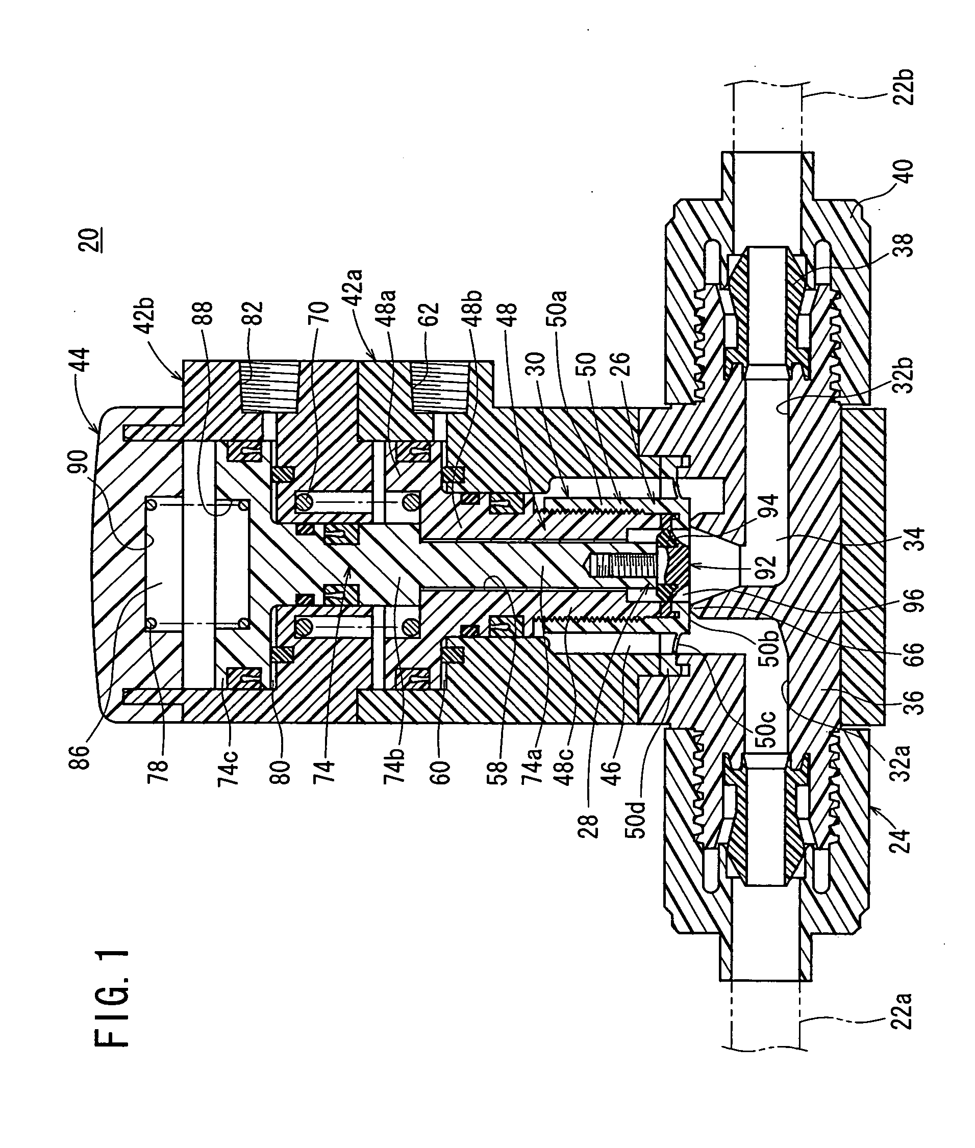
[0023] With reference to FIG. 1, reference numeral 20 indicates a suck back valve according to an embodiment of the present invention. The suck back valve 20 comprises a joint section 24 to which a pair of tubes 22a, 22b are detachably connected while being separated from each other by a predetermined spacing distance, and a valve-driving section 30 which is formed on the joint section 24 and which is constructed by integrally assembling an ON / OFF valve mechanism 26 and a suck back mechanism 28 arranged therein.

[0024] The joint section 24 includes a joint body 36 which has a first port 32a formed at one end and a second port 32b formed at the other end and which is provided with a fluid passage 34 for making communication between the first port 32a and the second port 32b, inner members 38 which are engaged with the first port 32a and the second port 32b respectively and which are inserted into openings of the tubes 22a, 22b, and lock nuts 40 which retain the liquid tightness or ai...


PUM


Abstract

A suck back valve includes an ON/OFF valve mechanism which opens/closes a fluid passage by displacing a valve member together with a first piston under an action of a pressure fluid supplied into a first cylinder chamber, and a suck back mechanism which has a suction member formed deformably in a flow chamber to suck a pressure fluid contained in the fluid passage by displacing the suction member together with a second piston under an action of the pressure fluid supplied to a second cylinder chamber. The ON/OFF valve mechanism and the suck back mechanism are assembled coaxially and integrally.

Description

BACKGROUND OF THE INVENTION [0001] 1. Field of the Invention [0002] The present invention relates to a suck back valve capable of avoiding any liquid drip, for example, from a supply port for a pressure fluid by sucking a predetermined amount of the pressure fluid flowing through a fluid passage. [0003] 2. Description of the Related Art [0004] A suck back valve has been hitherto used, for example, in steps for producing semiconductor wafers or the like. The suck back valve has a function to avoid the so-called liquid drip in which a minute amount of coating liquid is dripped from a supply port to the semiconductor wafer when the supply of the coating liquid to the semiconductor wafer is stopped. [0005] Such a conventional suck back valve is now shown in FIG. 5 (see, for example, Japanese Patent Publication No. 6-47092). [0006] The suck back valve 1 includes a main body 5 which is formed with a flow chamber 4 for making communication between an inflow port 2 and an outflow port 3, an...

Claims


Application Information

Patent Timeline
Patent Type & Authority Applications(United States)
IPC IPC(8): B05C5/00F16K11/02F16K23/00F16K31/122
CPCF16K31/1225F16K23/00F16K1/36F16K1/42F16K27/02H01L21/02002
Inventor FUKANO, YOSHIHIRO
Owner SMC CORP
Why Eureka
Try Eureka