
Method of fabricating semiconductor memory device and semiconductor memory device driver

Inactive Publication Date: 2005-01-13
MONTEREY RES LLC
View PDF8 Cites 4 Cited by
  • Summary
  • Abstract
  • Description
  • Claims
  • Application Information

AI Technical Summary

Benefits of technology

[0013] Taking into consideration the above, an object of the present invention is to provide a method of fabri

Problems solved by technology

This may cause a memory malfunction.
Further, if too many charges are stored, an insulating film that is in contact with the floating gate may be destroyed.
However, the conventional fabrication method has the following problems.
This causes corrosion of the aluminum metallization after etching.
These factors may cause corrosion.

Method used


Image

  • Method of fabricating semiconductor memory device and semiconductor memory device driver
  • Method of fabricating semiconductor memory device and semiconductor memory device driver
  • Method of fabricating semiconductor memory device and semiconductor memory device driver

Examples


Embodiment Construction

[0029] A description will now be given of embodiments of the present invention with reference to the accompanying drawings.

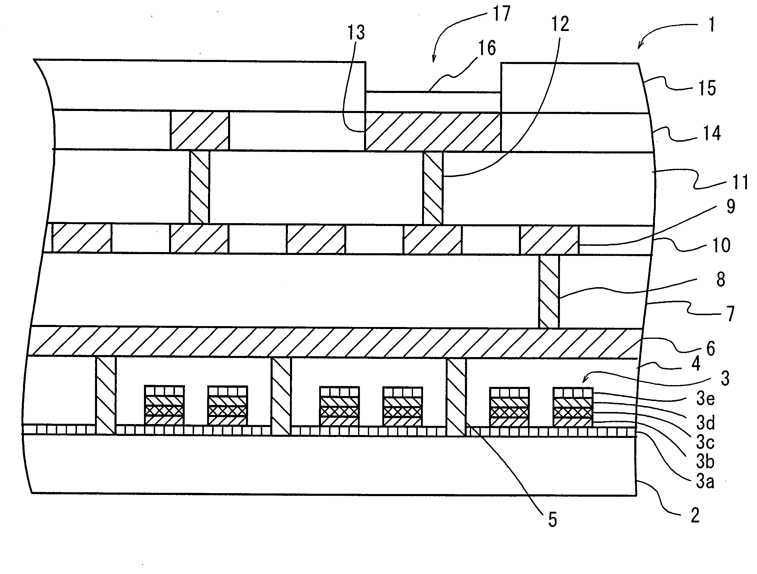
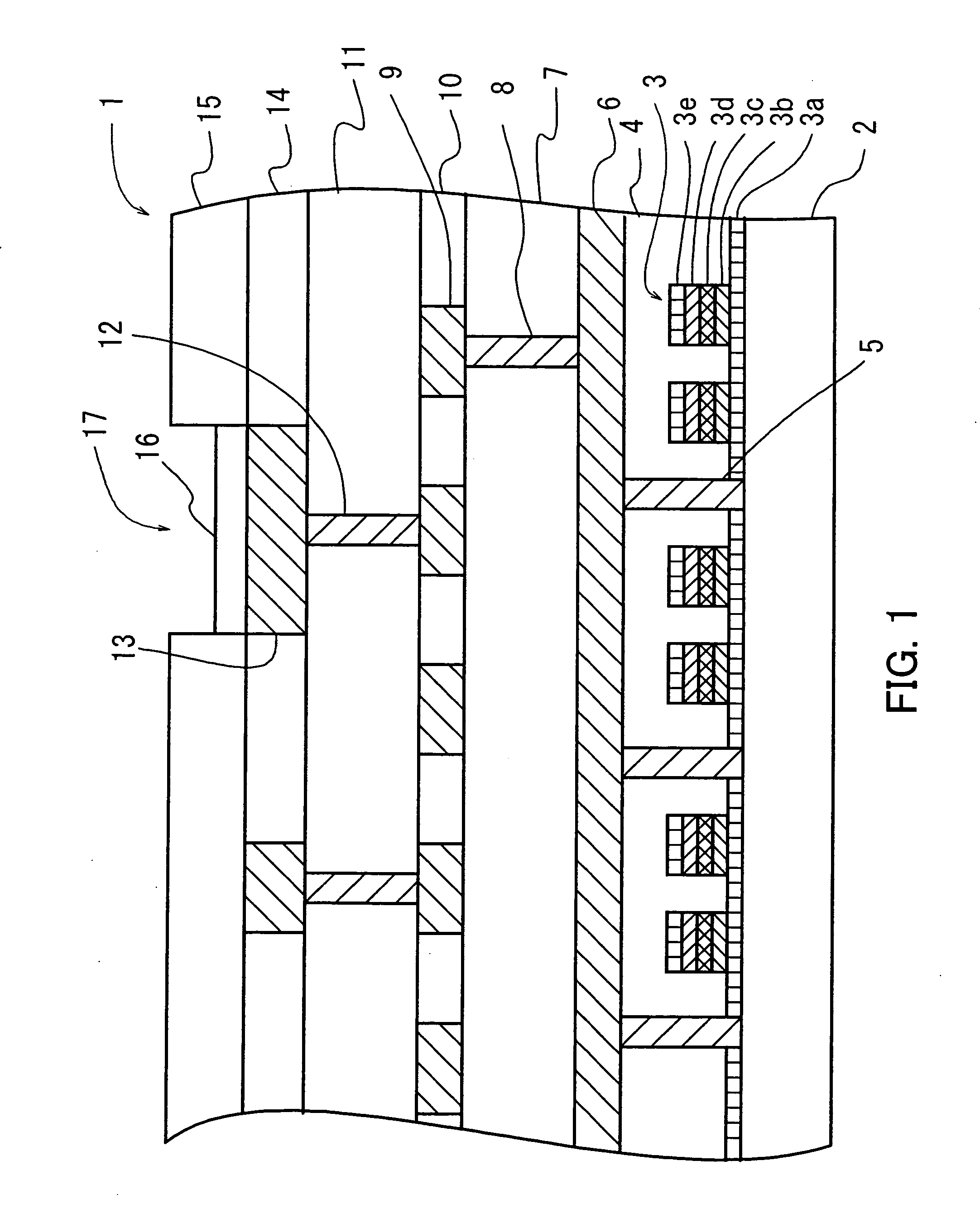
[0030]FIG. 1 shows a structure of the semiconductor memory device of the present invention. The semiconductor memory device that is assigned to a reference numeral of 1 in FIG. 1 has a structure of the flash memory.

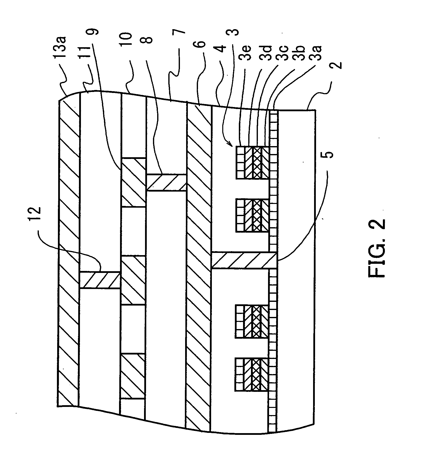
[0031] The structure of the semiconductor memory device 1 is described. Gates 3 are formed on a silicon (Si) substrate 2, and a film 4 for flattening is formed so as to cover the gates 3. Via wirings 5 are formed for making connections between the silicon substrate 2 and a metal interconnection 6. An interlayer insulating film 7 is formed on the metal interconnection 6. A via wiring 8 is formed to electrically connect the metal interconnection 6 and a metal interconnection 9 located above the interconnection 6. A film 10 for flattening is formed on the interlayer insulating film 7 so as to cover the metal interconnection 9. Another interlayer insula...


PUM


Abstract

Disclosed is a method of fabricating a semiconductor memory device including the step of irradiating ultraviolet rays on a metal interconnection at a bonding pad part, so that the metal interconnection can be prevented from being corroded because of a corrodent element in the process of erasing charges stored in a charge storage part. An oxide coating film is formed on the surface of the metal interconnection at the bonding pad part, and ultraviolet rays are irradiated onto the oxide coating film for erasing of charges from the floating gate.

Description

CROSS-REFERENCE TO RELATED APPLICATIONS [0001] This application is based upon and claims priority of Japanese Patent Application No. 2002-049438, filed on Feb. 26, 2002, the contents being incorporated herein by reference. BACKGROUND OF THE INVENTION [0002] 1. Field of the Invention [0003] The present invention relates to a method of fabricating a semiconductor memory device and a semiconductor memory device, and more particularly to a method of fabricating a non-volatile semiconductor memory device having the step of erasing charges cumulated in a charge storage part such as a floating gate by irradiating ultraviolet rays onto the surface of a metal wiring line of a bonding pad and such a semiconductor memory device. [0004] 2. Description of the Related Art [0005] Semiconductor memories using MOSFETs (Metal Oxide Semiconductor Type Field Effect Transistor) are generally used for storing digital data. Among these semiconductor memories, an EEPROM (Electrically Erasable Programmable ...

Claims


Application Information

Patent Timeline
IPC IPC(8): H01L21/28H01L21/3205H01L21/768H01L21/8247H01L23/485H01L23/52H01L27/10H01L27/105H01L27/115H01L29/423H01L29/43H01L29/49H01L29/788H01L29/792
CPCH01L21/02063H01L21/31133H01L2924/1306H01L2924/00014H01L2924/01033H01L2924/30105H01L2924/13091H01L21/31138H01L21/321H01L21/76801H01L21/76814H01L21/76834H01L24/02H01L24/03H01L24/05H01L27/105H01L27/115H01L27/11521H01L27/11526H01L27/11531H01L2224/05599H01L2224/05624H01L2224/05669H01L2924/01004H01L2924/01005H01L2924/01006H01L2924/01007H01L2924/01013H01L2924/01014H01L2924/01022H01L2924/01029H01L2924/0105H01L2924/01074H01L2924/01078H01L2924/01079H01L2924/04941H01L2924/05042H01L2924/00H10B41/42H10B41/40H10B69/00H10B41/30
Inventor HASHIMOTO, TATSUYAMAENOSONO, TOSHIYUKITOGAWA, TAIJIENDA, TAKAYUKITAKAGI, HIDEO
Owner MONTEREY RES LLC
Learn More