Synchronous rectifier circuit and power supply

a synchronous rectifier and power supply technology, applied in the field of power supply, can solve the problems of increased power loss, deterioration of power conversion efficiency, loss, etc., and achieve the effects of suppressing self-turn, increasing drive loss, and small loss

Active Publication Date: 2005-01-13
RENESAS ELECTRONICS CORP
View PDF4 Cites 3 Cited by
  • Summary
  • Abstract
  • Description
  • Claims
  • Application Information

AI Technical Summary

Benefits of technology

It is an object of the present invention to solve the above problems by providing a power supply having small loss and which can suppress the self-turn on phenomenon without increased drive loss.

Problems solved by technology

Accordingly, there is a problem that the power loss is produced by the diode and the power conversion efficiency is deteriorated.
Further, the power loss is increased and the temperature at the junction of the element rises and accordingly there is a problem that the larger the output current is, the more the commutation diodes 63 (2 or 3 diodes) are connected in parallel, so that it is necessary that the power loss per element is dispersed to suppress the junction temperature.
Accordingly, there is a problem that since the commutation MOSFET 3 having a small on resistance is selected, the feedback capacitance Crss thereof is increased, so that the self-turn on phenomenon is apt to occur.

Method used


Image

  • Synchronous rectifier circuit and power supply
  • Synchronous rectifier circuit and power supply
  • Synchronous rectifier circuit and power supply

Examples


Embodiment Construction

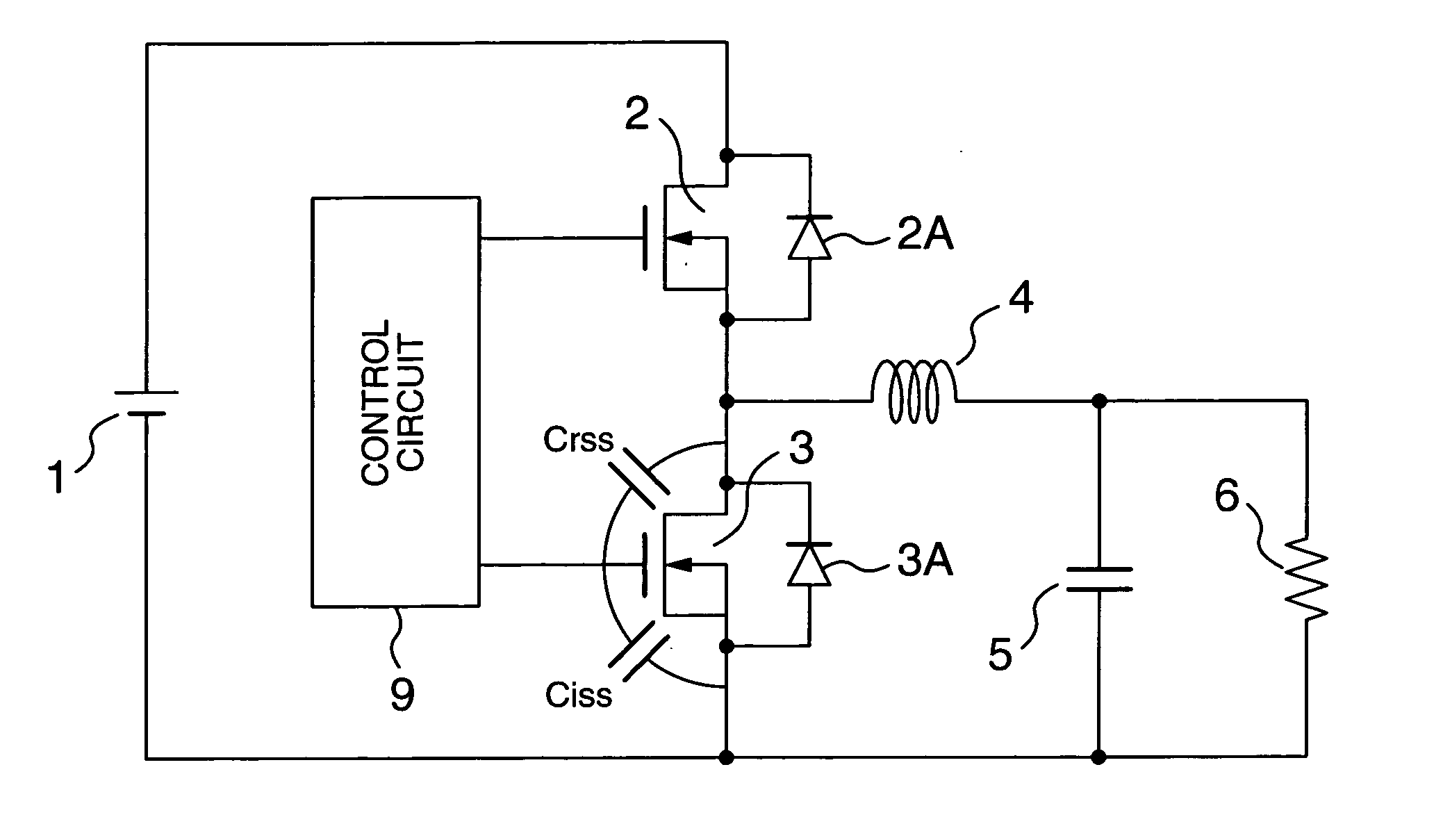
The present invention is now described in detail with reference to the accompanying drawings. A power supply of the present invention has the same circuit configuration as that of FIG. 5 used in description of the prior art. As shown in FIG. 5, the power supply of the present invention includes the rectification MOSFET 2 and the commutation MOSFET 3 and a DC input power supply 1 is connected to a drain terminal of the rectification MOSFET 2. A source terminal of the rectification MOSFET 2 is connected to one terminal of a choke coil 4 and a drain terminal of the commutation MOSFET 3. The other terminal of the choke coil 4 is connected to one terminal of a condenser 5 (for example, electrolysis condenser) and a load resistor 6. The other terminal of the condenser 5 is connected to a ground terminal.

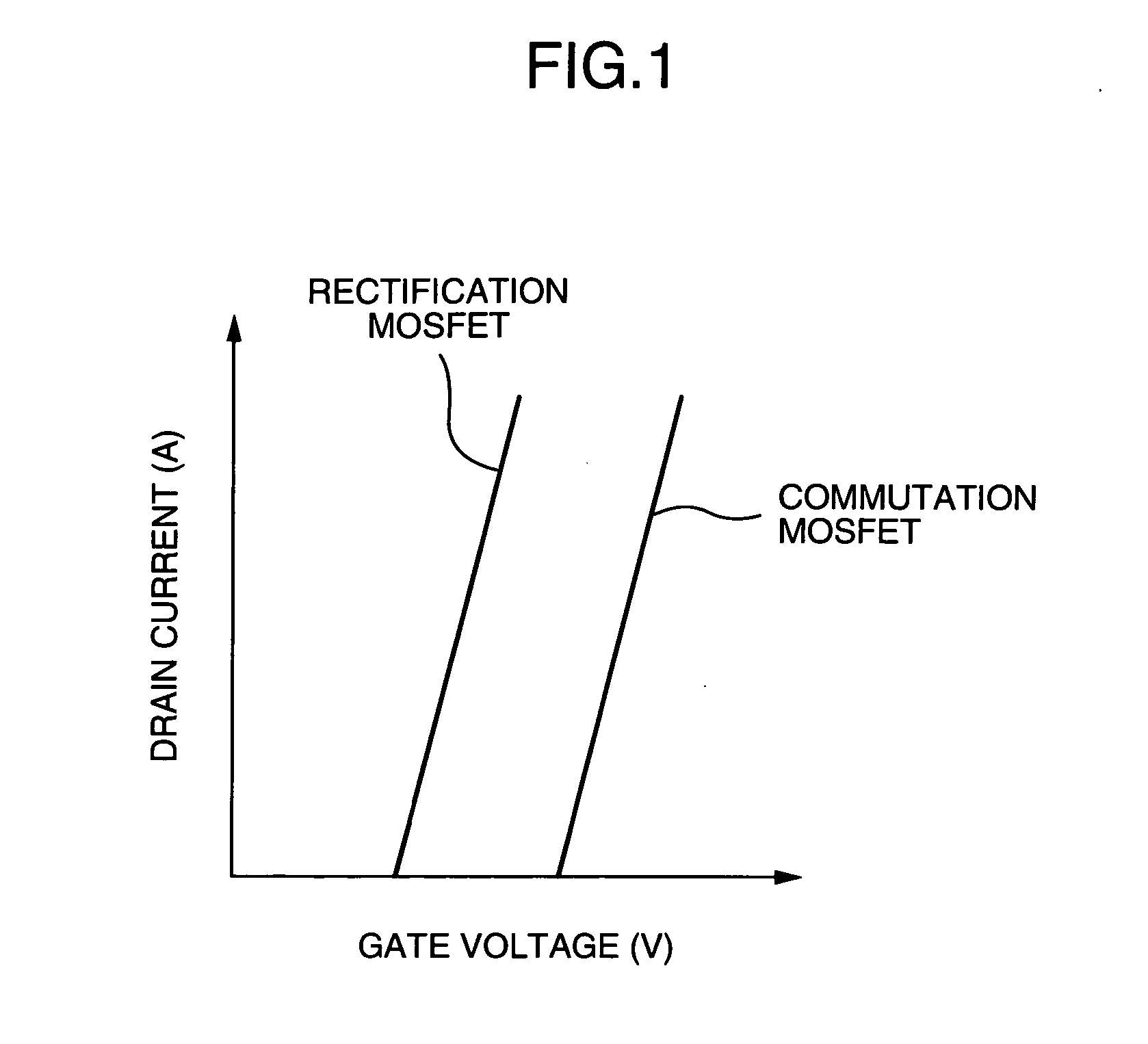
The threshold values of the rectification MOSFET 2 and the commutation MOSFET 3 used in the power supply of the present invention are shown in FIG. 1. In FIG. 1, the abscissa axis repre...


PUM


Abstract

In a power supply of a synchronous rectification type, the self-turn on phenomenon of MOSFET is suppressed without increase of the drive loss to thereby improve the power efficiency. In a synchronous rectifier circuit, a threshold value of a commutation MOSFET is made higher than that of a rectification MOSFET and particularly a threshold value of a commutation MOSFET 3 is made 0.5V or more higher than that of a rectification MOSFET 2. The threshold value of the rectification MOSFET 2 is lower than 1.5V and the threshold of the commutation MOSFET 3 is higher than 2.0V.

Description

BACKGROUND OF THE INVENTION The present invention relates to a power supply and more particularly to a synchronous rectifier circuit and a power supply used in electronic equipment. A conventional power supply as shown in FIG. 2 is known in which DC electric power inputted from a DC input power supply 60 to an input unit 51 including an input condenser 61 is switched by a switching unit 52 on the basis of a control signal produced by a driving unit 70 to supply electric power to a load 66 from an output unit 53 including a diode 63 and an output filter 55. Further, a voltage or a current supplied to the load 66 is detected by a detection unit 67 and the detected value is compared with a control target value for the load 66 set in a setting unit 68 by a comparison operation unit 69, so that the control signal based on its comparison result is supplied from a driving unit 70 to the switching unit 52. A definite circuit of the power supply of FIG. 2 is schematically illustrated in F...

Claims


Application Information

Patent Timeline
Patent Type & Authority Applications(United States)
IPC IPC(8): H02M7/21H02M3/155H02M3/158
CPCY02B70/1466H02M3/1588Y02B70/10
Inventor IWASAKI, TAKAYUKISAKAMOTO, KOZOSHIRAISHI, MASAKIMATSUURA, NOBUYOSHIUNO, TOMOAKI
Owner RENESAS ELECTRONICS CORP
Why Eureka
Try Eureka