Device for detecting the rotational speed and/or the position of a rotating component

a technology of rotating components and detectors, which is applied in the direction of measuring devices, speed/acceleration/shock measurement, instruments, etc., can solve the problems of high electric resistance of the layer system, the application of thin-layer layer sequences requires expensive equipment, and the use of materials exhibiting the cmr effect. , to achieve the effect of reducing costs

Inactive Publication Date: 2005-01-13
ROBERT BOSCH GMBH
View PDF8 Cites 28 Cited by
  • Summary
  • Abstract
  • Description
  • Claims
  • Application Information

AI Technical Summary

Benefits of technology

[0014] The device according to the present invention for detecting the rotational speed and/or the position of a rotating component, in which the magnetic field sensor has at least one sensor element made of a sensor material showing a CMR (colossal magneto resistance) effect, has the advantage that the sensor material may be manufac

Problems solved by technology

In a GMR sensor, the problem is that the application of the thin-layer layer sequence requires expensive equipment.
However, the GMR effect, like the TMR effect, is an extrinsic boundary surface effect for which a sensor element having a costly layer technology is necessary, since the sensor element is formed by several ultra-thin layers, only a few nanometers thick, that may partially be made of an alloy of

Method used


Image

  • Device for detecting the rotational speed and/or the position of a rotating component
  • Device for detecting the rotational speed and/or the position of a rotating component
  • Device for detecting the rotational speed and/or the position of a rotating component

Examples


Embodiment Construction

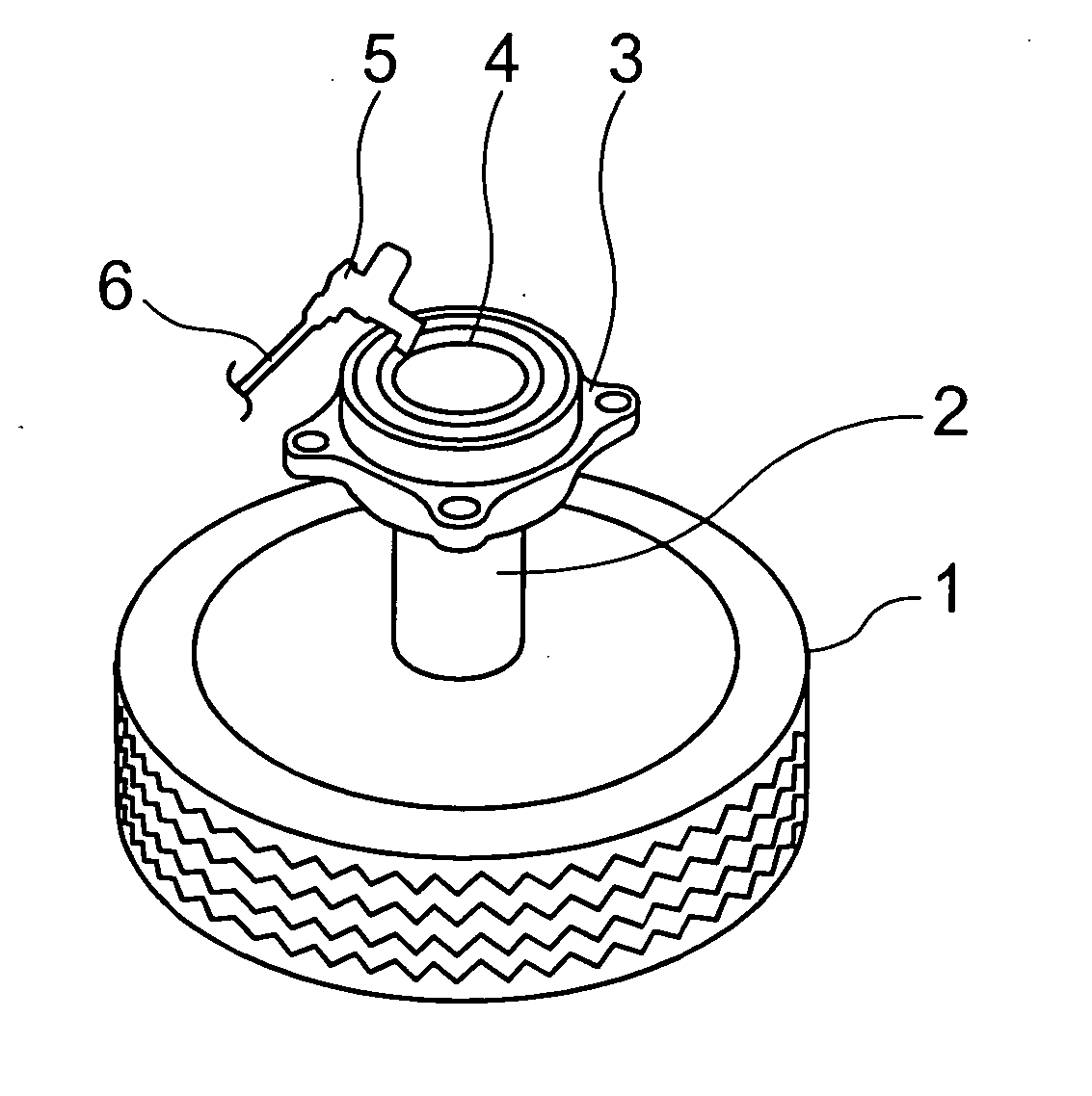
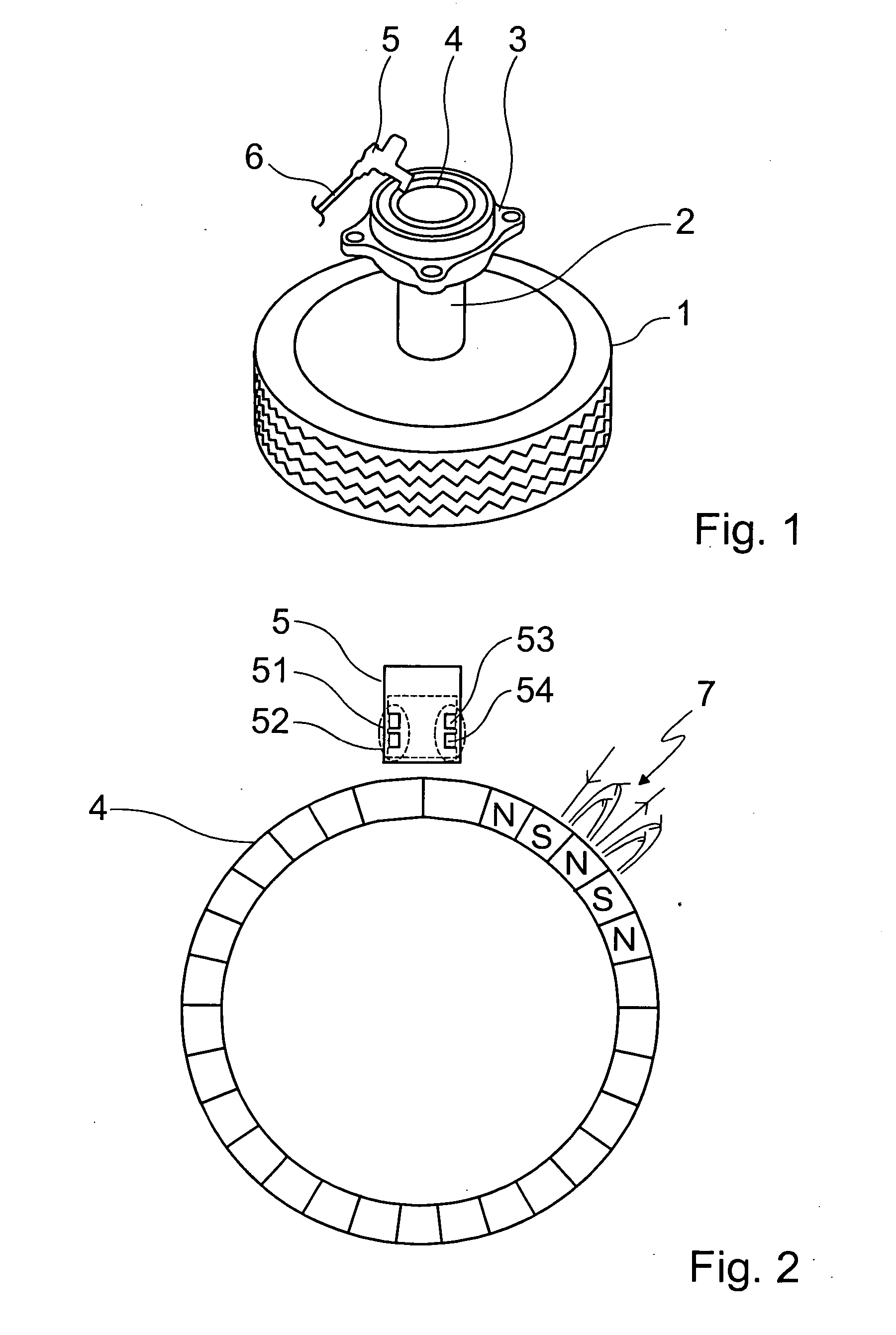
[0034]FIG. 1 shows wheel 1 of a vehicle, otherwise not shown in greater detail, connected to axis 2, which leads to a wheel bearing 3. Positioned in the area of wheel bearing 3 is a magnetic pole wheel 4, which is aligned concentrically with axis 2 and wheel 1, respectively, and coacts with magnetic field sensor 5, which is connected via a line 6 to a control unit not shown in greater detail.

[0035] As can be inferred from FIG. 2, pole wheel 4, which represents a magnetic sensor element, is made of alternately positioned magnetic north pole N and south pole S. Representative for the other areas of pole wheel 4, field lines are shown between each adjacent north and south pole for an area 7.

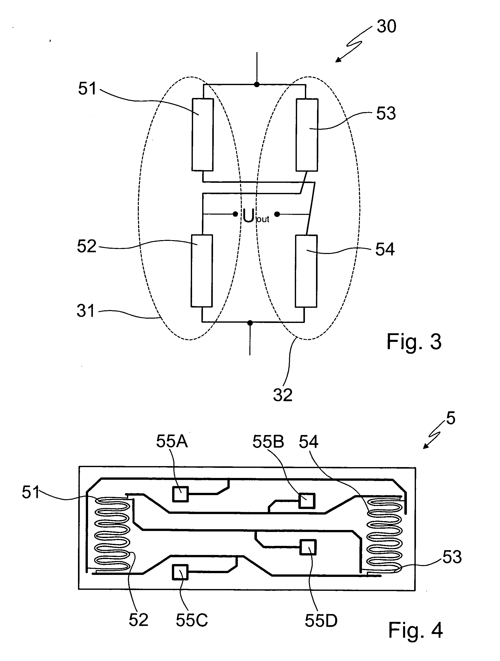
[0036] Magnetic field sensor 5, which coacts with pole wheel 4, is displaced in the radial direction of axis 2 opposite pole wheel 4 and may in practice be at a distance of about 10 mm from the latter, for example. Magnetic field sensor 5 includes four sensor elements 51, 52, 53 and 54, which act ...


PUM


Abstract

A device for detecting the rotational speed and/or the position of a rotating component, having at least one magnetic sensor element, which is securely connected to the rotating component, and a magnetic field sensor, which coacts with the sensor element and is designed to detect change in a magnetic field and is connected to an analyzing circuit. The magnetic field sensor includes at least one sensor element made of a sensor material exhibiting a CMR (colossal magneto resistance) effect.

Description

BACKGROUND INFORMATION [0001] A device is described in German Patent Application No. DE 196 47 420, for example, and is used to detect the rotational speed of a rotating component of a motor vehicle combustion engine. [0002] The known device is designed as a magnetoresistive device and represents a GMR (giant magneto resistance) sensor, which has a layer sequence made of ferromagnetic and non-magnetic thin layers, which coacts with a pulse-generating wheel designed as a magnetic pole wheel. The sensor is constructed in accordance with the principle of a Wheatstone bridge circuit, the four individual resistors of the bridge circuit each being formed by one GMR sensor element. The pulse-generating wheel and the sensor are positioned in relation to one another in such a way that the two bridge halves of the bridge circuit are situated in different magnetic fields, so that a differential mode voltage is applied at the bridge output. When the pulse-generating wheel is turned, the magneti...

Claims


Application Information

Patent Timeline
IPC IPC(8): G01D5/14G01D5/16G01P3/487
CPCG01P3/487G01D5/145
Inventor SIEGLE, HENRIKRABE, MAIKMAY, ULRICH
Owner ROBERT BOSCH GMBH
Why Eureka
Try Eureka