Multi-channel optical switch

a multi-channel optical switch and optical switch technology, applied in optics, instruments, optical light guides, etc., can solve the problems of light transmission loss, micro-machined optical switches are big problems, etc., and achieve the effect of reducing reflection loss and reducing insertion loss

Inactive Publication Date: 2005-01-13
SAEHYUP +1
View PDF1 Cites 55 Cited by
  • Summary
  • Abstract
  • Description
  • Claims
  • Application Information

AI Technical Summary

Benefits of technology

[0018] Preferably, to decrease the insertion loss of the respective waveguides, the optical waveguide having an expanded core may be used, an end facet of each of the waveguides may be made in the form of lens, an antireflective film may be coated on the end facet of each of the waveguides, or a refractive index matching liquid, a separate optical waveguide or a lens may be provided between the waveguides. Also, to reduce reflection loss of the pairs of optical waveguides, refractive index matching liquid or antireflection coating may be provided to the end facet of each of the pairs of optical waveguides, or each of the optical waveguides may have a facet beveled at an angle of 3 degrees to 20 degrees.

Problems solved by technology

Micromachined optical switch is big issue because its usual insertion losses, crosstalk, wavelength dependent losses, polarization dependent losses are lower than any other switching mechanism.
In other words, the light is reflected separately by a distance 411 as much as 1 / {square root}{fraction (2)} of thickness of the first mirror by the first mirror, and the reflection separation is increased by a distance 412 as much as 2 / {square root}{fraction (2)} of thickness of the second mirror index matching, resulting in light transmission loss.

Method used


Image

  • Multi-channel optical switch
  • Multi-channel optical switch
  • Multi-channel optical switch

Examples


Embodiment Construction

[0025] The present invention will now be described more fully with reference to the accompanying drawings, in which exemplary embodiments of the invention are shown

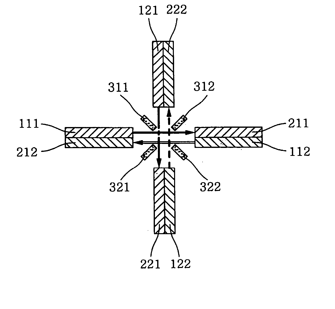
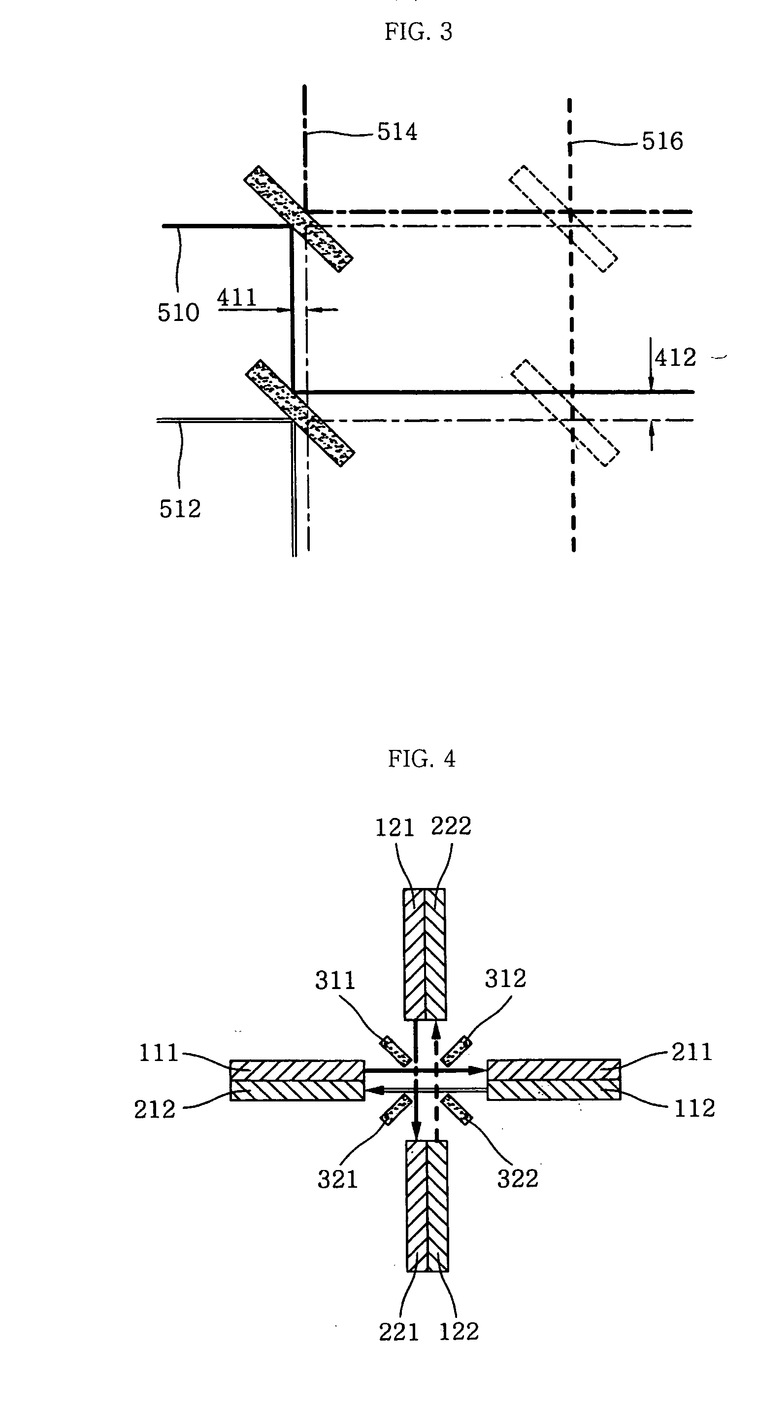
[0026]FIG. 4 is a schematic view of a multi-channel optical switch according to an embodiment of the present invention. Referring to FIG. 4, the multi-channel optical switch includes two pairs of input and output ports 111 and 212, and 211 and 112 for inputting and outputting light, two pairs of add and drop ports 121 and 222, and 221 and 122 for inputting and outputting light, mirrors 311, 312, 313 and 314, which enter or emerge in an optical path direction between the pairs of ports 111 and 212, 211 and 112, 121 and 222, and 221 and 122 to change the optical path direction, and a driving unit (not shown) for controlling the entering and emerging of the mirrors 311, 312, 313 and 314. The names or functions of the input port, the output port, the add port and the drop port may be changed according to their use.

[0027] In...


PUM


Abstract

An optical switch enabling optical communications between an input port and an output port of an optical waveguide by minimizing loss error of an optical signal without using a collimator comprised of a separate mediate optical waveguide, lens or the like is provided. The multi-channel optical switch, which changes optical paths, includes four pairs of input optical waveguides and output optical waveguide arranged in parallel to each other, the first pair of input optical waveguide and output optical waveguide facing the second pair of input optical waveguide and output optical waveguide at an angle of 90 degrees, the first input optical waveguide being installed to correspond to the second output optical waveguide, four mirrors installed to enter in optical path directions between the four pairs of input optical waveguides and output optical waveguides, thereby changing the optical paths, and a mirror actuator for selectively operating the entering of the mirror.

Description

BACKGROUND OF THE INVENTION [0001] 1. Field of the Invention [0002] The present invention relates to a multi-channel optical switch used in a wavelength division multiplex (WDM) optical communication system, and more particularly, to an optical switch enabling optical communications between an input port and an output port of an optical waveguide by minimizing loss error of an optical signal without using a collimator comprised of a separate mediate optical waveguide, lens or the like. [0003] 2. Description of the Related Art [0004] Generally, multiple channel signals are transmitted by light with several wavelengths in the WDM optical fiber communication. Single mode fibers supporting light signals with the wavelength of 1.3 or 1.55 um are widely used for this optical fiber communication because of low transmission loss. [0005] The apparatus for implementing the WDM is called ‘Wavelength division multiplexer’ and functions as a kind of optical coupler, which makes one optical fiber...

Claims


Application Information

Patent Timeline
Patent Type & Authority Applications(United States)
IPC IPC(8): G02B6/35G02B26/08
CPCG02B6/3514G02B6/355G02B6/3546G02B26/08
Inventor KIM, SEON-JUKWON, HO-NAMLEE, JONG-HYUNKIM, WON-HYOPARK, JONG-SAM
Owner SAEHYUP
Why Eureka
Try Eureka