Aluminide coating of turbine engine component

a technology of turbine engines and components, applied in the direction of solid-state diffusion coatings, vacuum evaporation coatings, coatings, etc., can solve the problems of premature failure of the blades of the engine, high cost and difficulty in controlling

Inactive Publication Date: 2005-01-13
GENERAL ELECTRIC CO
View PDF27 Cites 32 Cited by
  • Summary
  • Abstract
  • Description
  • Claims
  • Application Information

AI Technical Summary

Problems solved by technology

However, if the coating is applied at too great a thickness on regions of the blade operating at lower temperatures, such as the root and shank region, the combination of the increased coating thickness and the abrupt transition within the dovetail may cause cracking in the root portion as higher stresses are induced into the transition area of the dovetail.
Over time, continued operation may lead to a premature failure of the blade within the engine.
While the above processes can be used to form an aluminide coating on the exterior and interior surfaces of turbine blades, processes using halide containing vapors at high deposition temperatures can be expensive and difficult to control, and may result in distortion of the blades, grain growth, creep and other thermo-mechanical failure mechanisms that can decrease the strength and life of the blade.

Method used


Image

  • Aluminide coating of turbine engine component
  • Aluminide coating of turbine engine component
  • Aluminide coating of turbine engine component

Examples


example 1

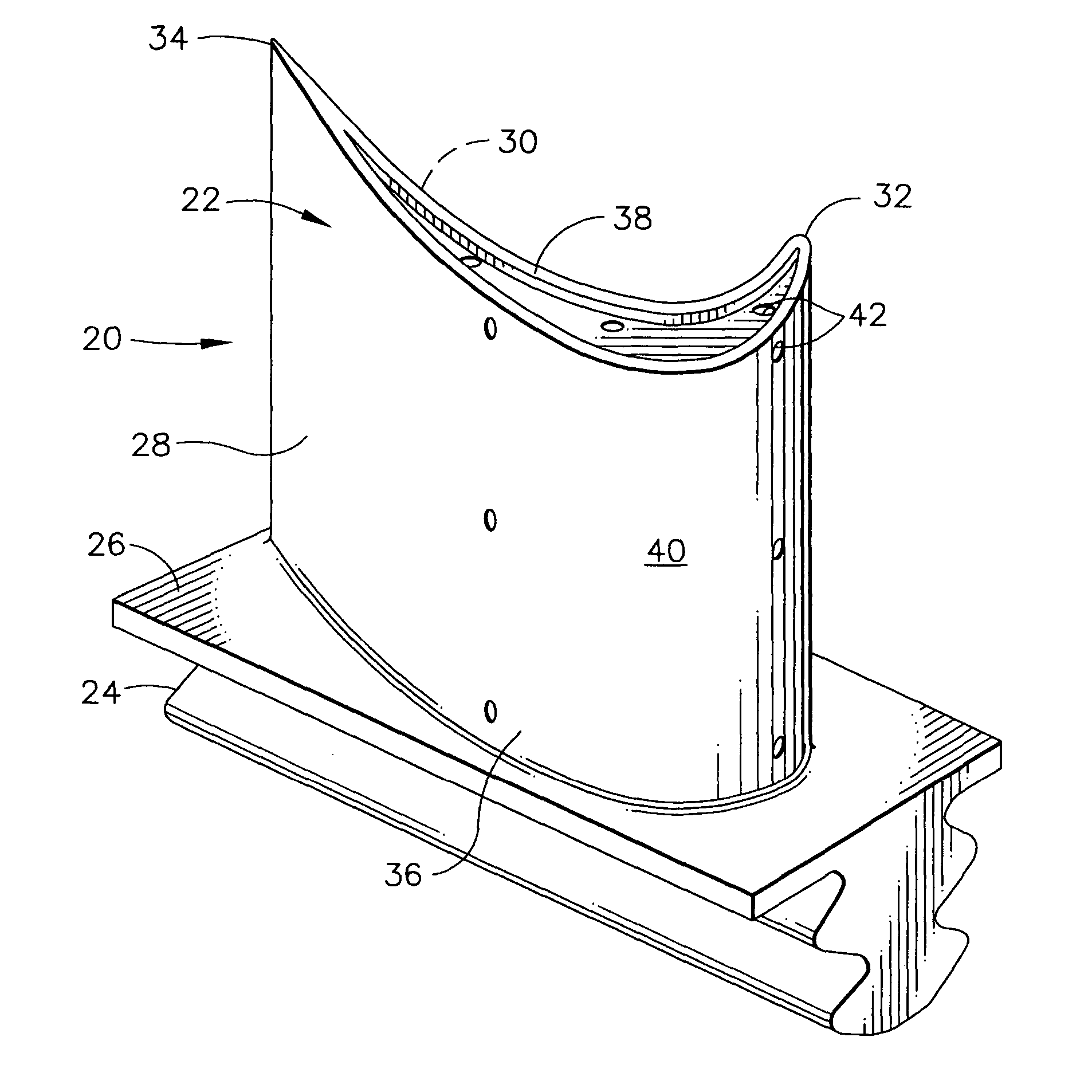
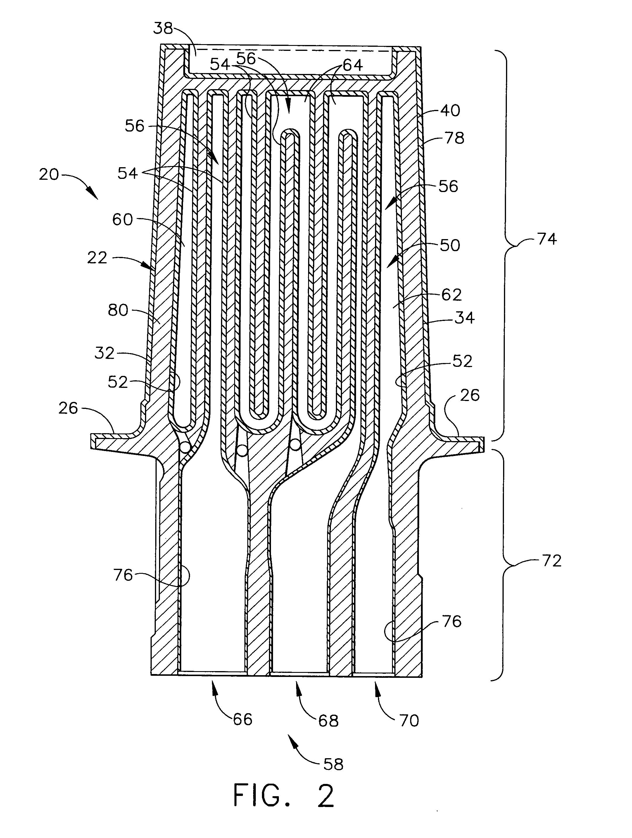
[0046] A process of the present invention is used to form an aluminide coating to turbine blades in the coating container shown in FIG. 3. The blades are loaded into the coating container and heated to a temperature of about 270° C. A tri-n-butyl aluminum coating gas is then flowed into the coating container at a pressure of about 500 mtorr (about 6.8 kgf / m2) for about 5 hours to force the aluminum coating vapors to flow around the blades and through the cooling holes and internal cooling cavities of the blades, thereby depositing an aluminum coating on the external and internal surfaces of the blades. Some of the aluminum coating gas is ducted into the dovetail portions of the blades so that the vapor flows through their internal cooling cavities and out their cooling holes. The thickness of the aluminum coating is controlled by the temperature, gas flow, and elapsed time of the gas flow. The coated blades are then heated in a vacuum to a temperature of about 670° C. for about 5 ho...

example 2

[0048] A process of the present invention is used to form an aluminide coating to turbine vanes in the coating container shown in FIG. 3. The vanes are loaded into the coating container and heated to a temperature of about 450° C. A tri-n-butyl aluminum coating gas is then flowed into the coating container at a pressure of about 100 mtorr (about 1.4 kgf / m2) for about 1 hour to force the aluminum coating vapors to flow around and through the vanes, thereby depositing an aluminum coating on the external and internal surfaces of the vanes. Some of the aluminum coating gas is ducted into the internal cooling cavities of the vanes so that the vapor flows through the cooling cavities and out the cooling holes. The thickness of the aluminum coating is controlled by the temperature, gas flow, and elapsed time of the gas flow. The coated vanes are then heated in a vacuum to a temperature of about 670° C. for about 1 hour to form an aluminide coating on the external and internal surfaces of t...


PUM

PropertyMeasurementUnit
temperatureaaaaaaaaaa
pressureaaaaaaaaaa
temperatureaaaaaaaaaa

Abstract

A method for forming an aluminide coating on a turbine engine component having an external surface and an internal cavity defined by an internal surface that is connected to the external surface by at least one hole. The method is conducted in a vapor coating container having a hollow interior coating chamber, and includes the steps of loading the coating chamber with the component to be coated; flowing a tri-alkyl aluminum coating gas into the loaded coating chamber at a specified temperature, pressure, and time to deposit an aluminum coating on the external and internal surfaces of the component; and heating the component in a nonoxidizing atmosphere at a specified temperature and time to form an aluminide coating on the external and internal surfaces. The coated component is typically then maintained at an elevated temperature in the presence of oxygen to form an oxide coating on the external and internal surfaces of the component. In one embodiment, the turbine engine component is a turbine engine blade having an external surface and an internal cooling cavity having an internal surface that is connected to the external surface by cooling holes.

Description

BACKGROUND OF THE INVENTION [0001] The present invention relates to a method for forming a protective coating on a turbine engine component having an external surface and an internal cavity defined by an internal surface connected to the external surface by at least one hole. More particularly, the invention relates to forming an aluminide coating on the internal and external surfaces of a turbine component, such as a turbine blade having an internal cooling cavity. [0002] In an aircraft gas turbine engine, air is drawn into the front of the engine, compressed by a shaft-mounted compressor, and mixed with fuel. The mixture is burned, and the hot exhaust gases are passed through a turbine mounted on the same shaft. The flow of combustion gas turns the turbine by impingement against the airfoil section of the turbine blades, which turns the shaft and provides power to the compressor. (As used herein, the term turbine blade may refer to either a turbine blade or a turbine vane, which h...

Claims


Application Information

Patent Timeline
Patent Type & Authority Applications(United States)
IPC IPC(8): C23C10/08C23C16/04C23C16/20C23C16/56
CPCC23C10/08C23C16/045Y02T50/67C23C16/56C23C16/20Y02T50/60
Inventor ACKERMAN, JOHN FREDERICKWEIMER, MICHAEL JAMESHEANEY, JOSEPH ALOYSIUSWALSTON, WILLIAM SCOTTNAGARAJ, BANGALORE ASWATHA
Owner GENERAL ELECTRIC CO
Why Eureka
Try Eureka