

Method of constructing a capacitor stack for a flat capacitor
a flat capacitor and capacitor technology, applied in capacitor manufacture, variable capacitors, therapy, etc., can solve the problems of warpage of capacitor elements, increased height to the assembly, unneeded residual stresses, etc., to reduce the variation in the outer dimensions of one capacitor stack to another capacitor stack, increase the anodic surface area, and increase the capacitance
- Summary
- Abstract
- Description
- Claims
- Application Information
AI Technical Summary
Benefits of technology
Problems solved by technology
Method used
Image

Examples
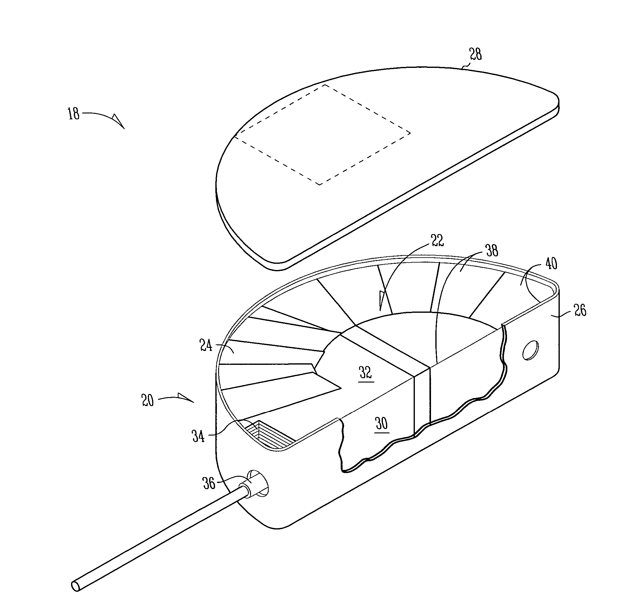
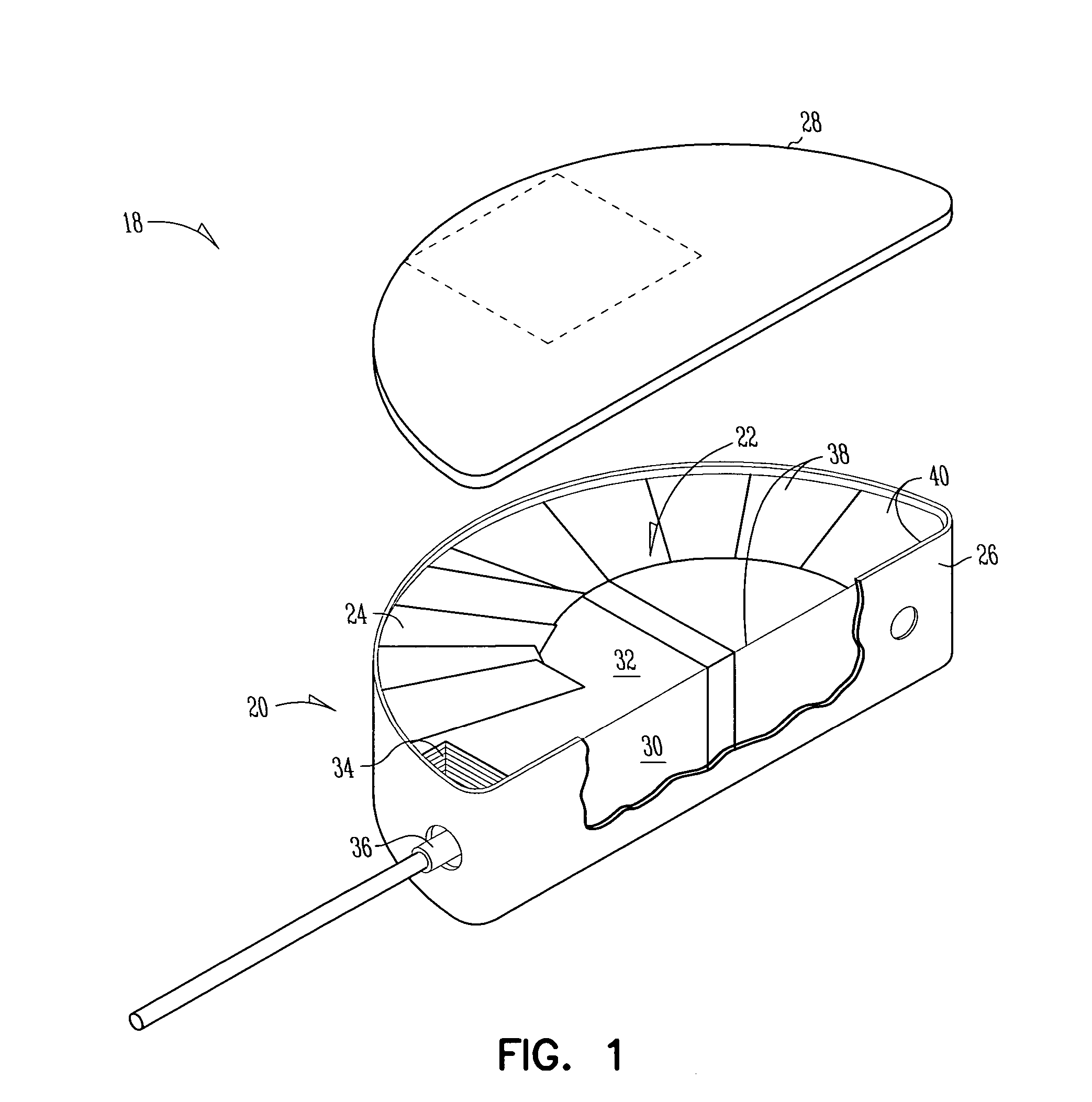
case 20
Case 20 includes a base 26 and a lid 28 overlying and resting on an upper rim of base 26. Stack 24 has a face 30 and a top surface 32. Stack 24 has a cutout region 34 at its periphery, with cutout region 34 being positioned when the stack 24 is installed in case 20 to provide space for electrical connections. An anode feedthrough post 36 passes through to stack 24 and is electrically insulated from case 20. The capacitor stack 24 is covered with insulating tape 38. A space 40 exists between the lid 28 and the top surface 32 of the stack 24 and between the face 30 of the stack 24 and a lateral wall of the base 26 of the case 20. In some embodiments, space 40 is a line-to-line interference fit between portions of stack 24 and case 20. In other embodiments, space 40 is a gap or opening within the case and between the stack and the case.
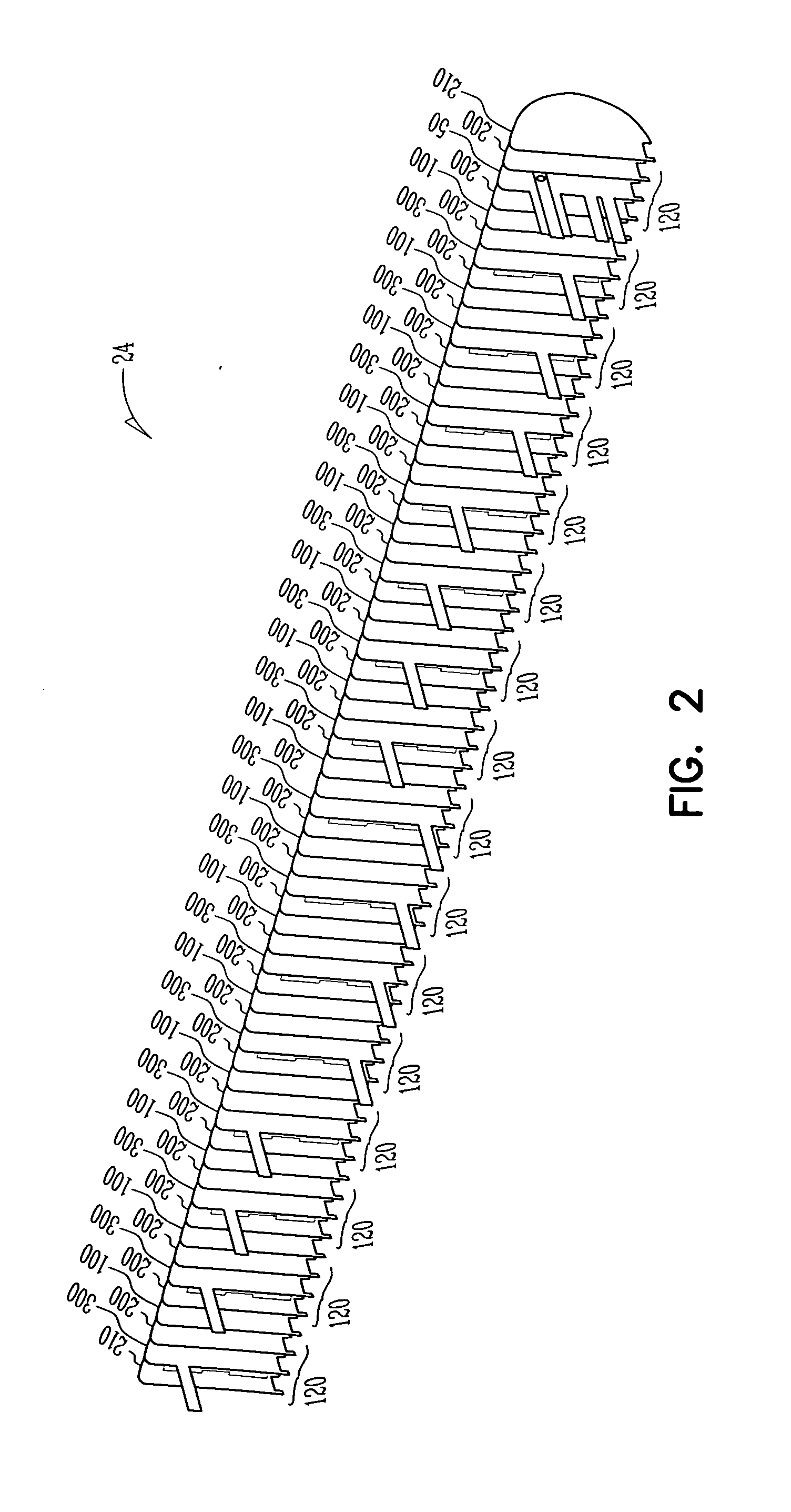
Capacitor stack 24 includes anode assemblies and cathode assemblies, with separator layers interposed therebetween.
FIG. 2 illustrates an exploded view...
PUM
 Abstract
Description
Claims
Application Information