
Tamper evident packaging

a technology of tamper evident packaging and packaging parts, applied in the direction of instruments, electric signalling details, mechanical action of burglar alarms, etc., can solve the problems of less security of the system and the difficulty of an opponent to avoid breaking traces, and achieve the effect of higher precision

Active Publication Date: 2005-01-20
SONY CORP
View PDF6 Cites 32 Cited by
  • Summary
  • Abstract
  • Description
  • Claims
  • Application Information

AI Technical Summary

Benefits of technology

[0013] The basic principle for detecting the integrity of the packaging relies on continuous monitoring of the resistance of the printed traces. In a simplified form, it would be sufficient to monitor if a trace is broken or not. A continuous trace is then considered a non-tampered packaging and a broken trace a tampered packaging. But this simplified approach would make the system less secure, as an opponent could possibly understand the design and layout of the conductive traces. Such an opponent could then bypass a trace with an external conductor and then open the packaging without detection. In contrast, if the resistance of the traces is measured as an analog value, any change in resistance can be considered to be a second level of alarm event. However, the analog measurement approach must take in account the possible natural changes in resistance, due to aging, humidity, temperature and other sources of drift, which could potentially trigger a false alarm. By printing additional reference traces, the relative change in resistance between the traces, which are to be monitored, and the reference traces gives a more reliable measurement and minimizes the risk of false alarms.
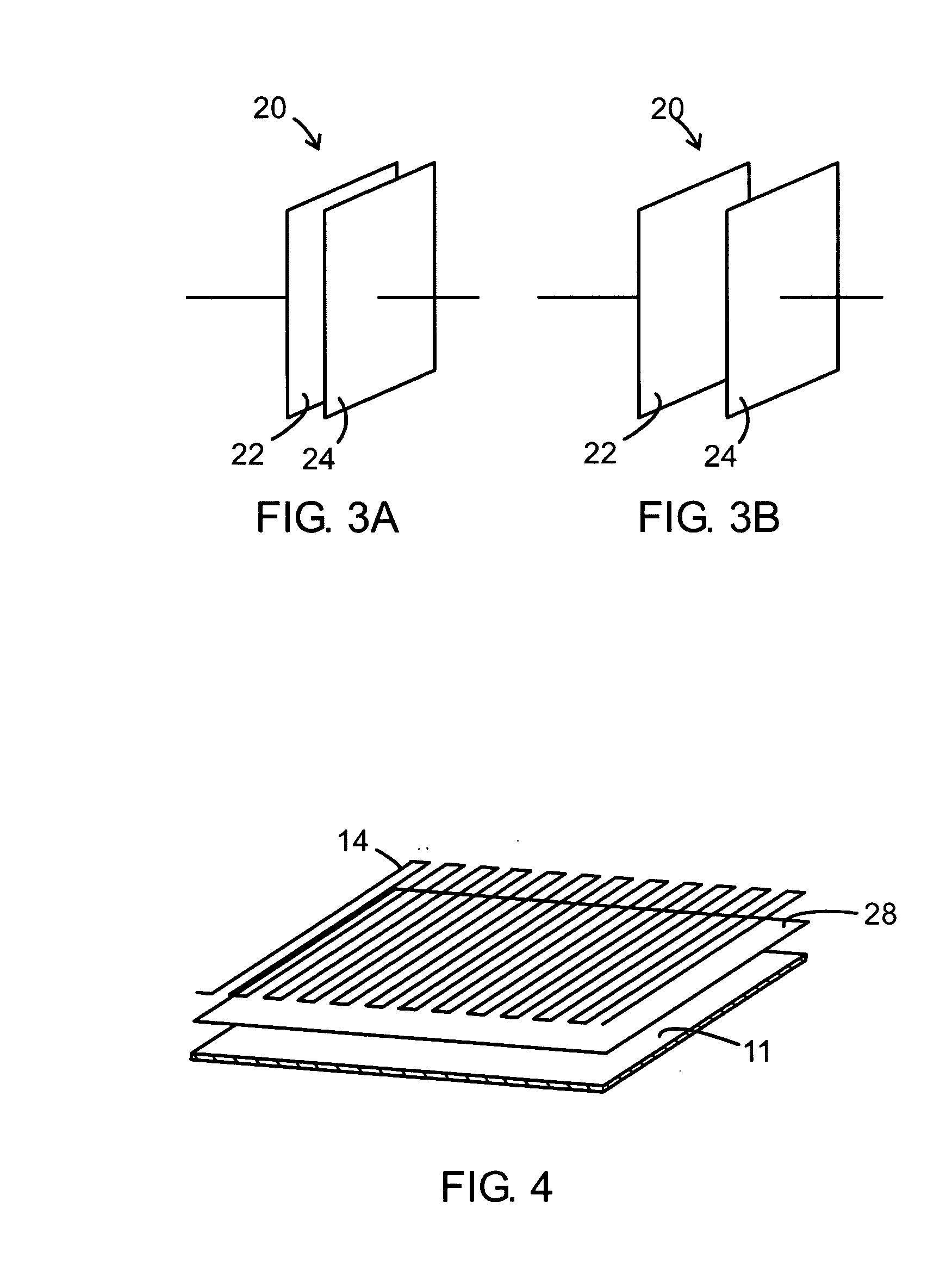
[0014] The printed sensors can also extend over areas with recesses, which are designed to break more easily than corresponding continuous area of packaging material. Such areas, when present in closing lids or flaps with adhesive, makes it more difficult for an opponent to avoid breaking traces when illegally opening the packaging.
[0015] Further, by at least partial, preparing the substrate prior to printing with a varnish, which gives excellent adhesion to the substrate, but gives moderate to low adhesion to the printed traces, enables the traces to break or degrade more easily when tampered. In combination with the recesses mentioned above, the sensitivity of the detection of the conductive traces can easily be tailored to fit a particular application.
[0025] In applications where the temperature must be within a specific range, such as transportation of certain types of food, pharmaceuticals, chemicals, etc., a temperature sensor may be included in the electronic module. Continuous monitoring and recording of the ambient temperature into the memory means, creates a reliable audit trail, which can be retrieved and checked at time of the shipment's arrival to the receiver.
[0026] In summary, the invention described above, introduces a powerful and flexible platform for monitor a shipment in a logistics chain. By continuous monitoring of critical parameters, a reliable audit trail is generated, which can be further signed using cryptographic methods, to verify the authenticity of the information and the shipment itself. Disputes between a sender and receiver and cases of non-repudiation can be resolved with a higher precision.

Problems solved by technology

But this simplified approach would make the system less secure, as an opponent could possibly understand the design and layout of the conductive traces.
However, the analog measurement approach must take in account the possible natural changes in resistance, due to aging, humidity, temperature and other sources of drift, which could potentially trigger a false alarm.
Such areas, when present in closing lids or flaps with adhesive, makes it more difficult for an opponent to avoid breaking traces when illegally opening the packaging.

Method used


Image

  • Tamper evident packaging
  • Tamper evident packaging
  • Tamper evident packaging

Examples


Embodiment Construction

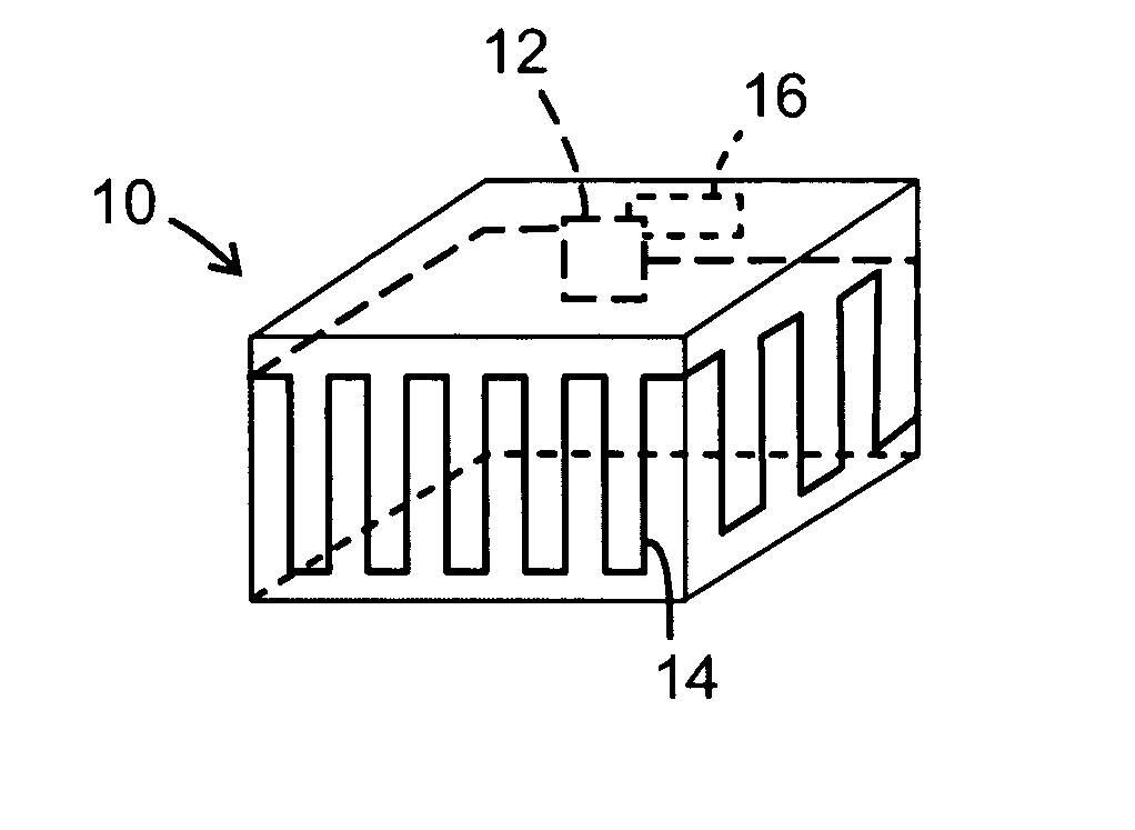
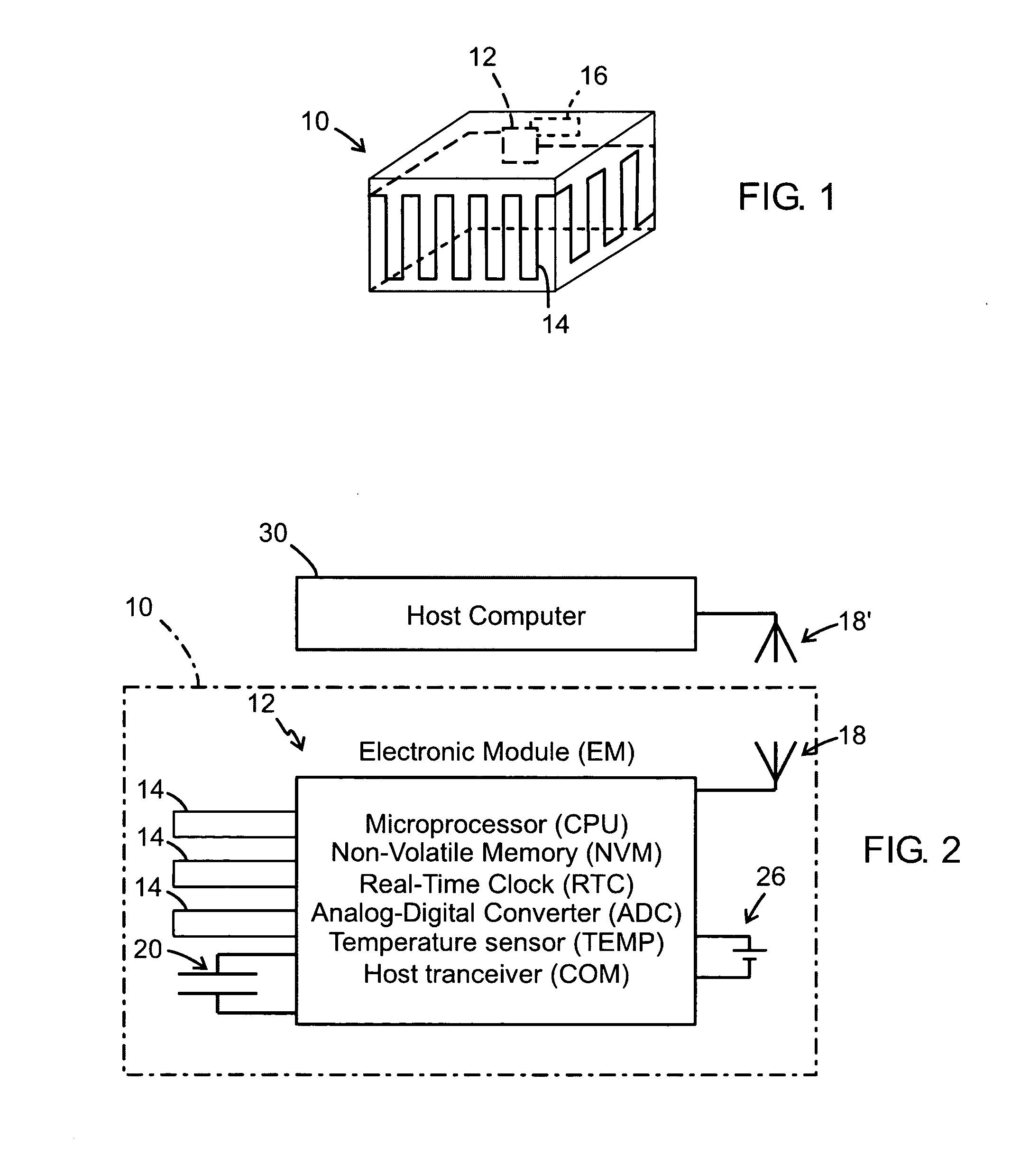
[0031] The preferred embodiment comprises a packaging for a shipment (FIG. 1) more precisely a cardboard parcel 10. The packet is printed with a plurality of traces 14 (all traces not shown for clarity in the FIG. 1), using electrically conductive ink to form an integral part of the package. The traces extend over all areas of the parcel. If a physical damage occurs which ruptures the cardboard, the conductivity of at least one of the traces is significantly changed. An integrated Electronics Module (EM) 12, also attached to the pack-age to form an integral part thereof, continuously monitors the conductivity of the traces. Any significant change in conductivity is considered an alarm event, which is stored in a memory in the EM 12. In order to compensate for drift in the electric conductivity in traces, a reference trace 16 is included. Rather than measuring the absolute value of the resistance of traces 14, the relationship between the trace to be measured 14 and the reference tra...


PUM


Abstract

A packaging and a method for monitoring a packaging (10) of a disposable material in a chain of logistics. As an integral part of the packaging, the packaging has an electronic module (12) comprising electric energy supply means, data processing means, data storage nonvolatile memory means for storing information related to the packaging, time keeping means, and data transceiver means for transmitting and receiving said information in communication with a host computer (30). The electronic module also has sensor means (14, 20) for detecting a changed physical condition of the packaging and for signaling information representing said changed physical condition to the electronic module (12) to be stored in the memory means together with a notation of time from the time keeping means.

Description

RELATED APPLICATION DATA [0001] This application claims the benefit of U.S. Provisional Application No. 60 / 452,447 filed Mar. 6, 2003, which is hereby incorporated herein by reference in its entirety.FIELD OF THE INVENTION [0002] The present invention is concerned with secure and tamper evident packaging. Specifically, the invention is directed to a packaging of a disposable material and a method for monitoring the packaging particularly during shipment in a chain of logistics. BACKGROUND OF THE INVENTION [0003] Damage of goods in transportation is a major problem in the field of logistics. When a shipment is received in a damaged condition, there are usually no possibilities to track when the damage occurred, which turns the question of liability into an open question. [0004] Further, intrusion and tamper events, such as illegal opening and / or modification of the content of the shipment are major concerns when handling valuable or sensitive goods. Theft, where valuable items are re...

Claims


Application Information

Patent Timeline
Patent Type & Authority Applications(United States)
IPC IPC(8): B65B61/00G06Q10/00G08B13/26
CPCB65B61/00G08B13/126G06Q10/08G06K19/07798
Inventor EHRENSVARD, JAKOBEHRENSVARD, STINAERIKSSON, LEIFEINBERG, FREDRIK
Owner SONY CORP
Learn More