Laser welding unit

Inactive Publication Date: 2005-01-20
FANUC LTD
View PDF6 Cites 26 Cited by
  • Summary
  • Abstract
  • Description
  • Claims
  • Application Information

AI Technical Summary

Benefits of technology

According to the present invention, the laser welding unit is constituted as stated above, whereby the plasma beam generated in the welding target section during the laser w

Problems solved by technology

It is, therefore, often difficult to maintain welding quality stable.
With this conventional method, however, an attitude of the machine tool is restricted because of the arrangement of the optical sensor near the welding target or on the

Method used


Image

  • Laser welding unit
  • Laser welding unit
  • Laser welding unit

Examples


Embodiment Construction

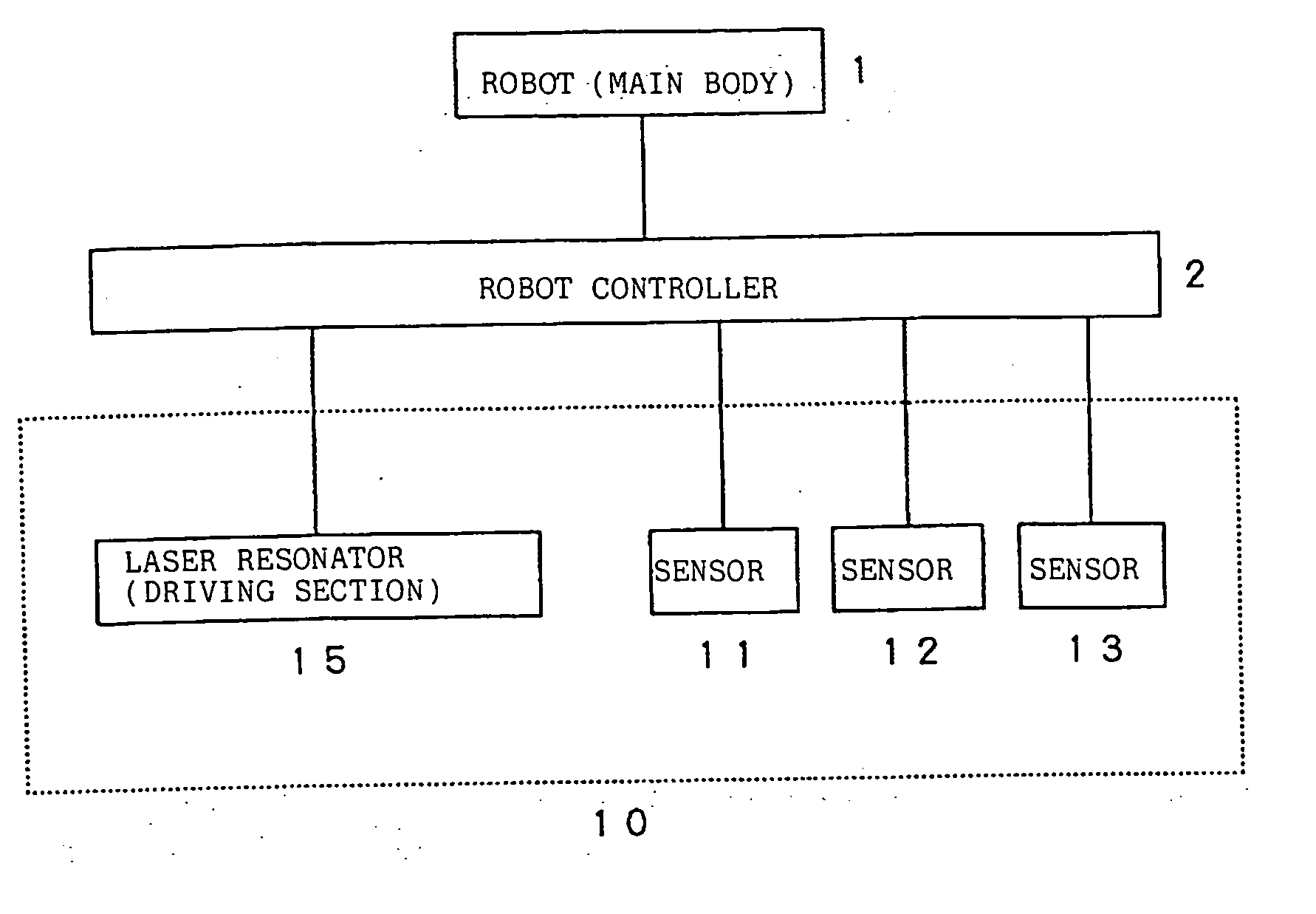
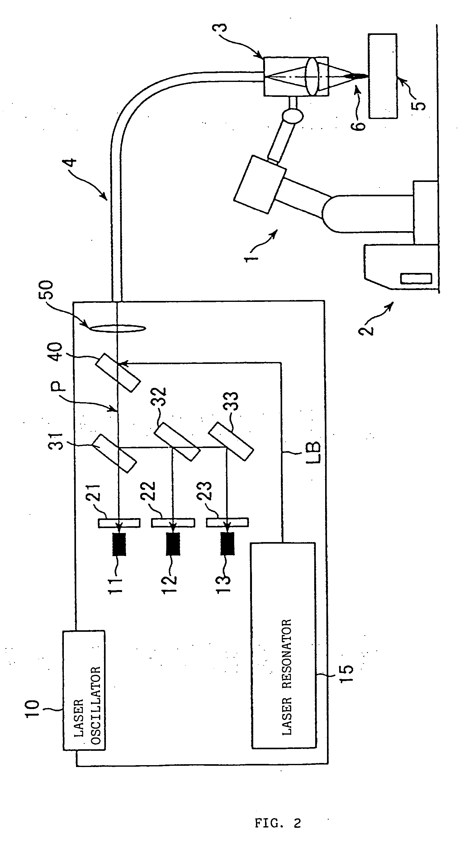
As shown in FIGS. 1 and 2, according to one embodiment of the present invention, a laser welding torch 3 is mounted, as a welding tool, on a tip end of an arm of a robot (main body) 1 controlled by a robot controller 2, and a welding target workpiece 5 is welded. A laser beam is supplied to the laser welding torch 3 from a laser oscillator 10 through an optical fiber 4.

When a welding laser beam is irradiated from the laser welding torch 3 onto a surface of a welding target workpiece 5, a plasma 6 is generated in a laser irradiated section, as is well known. According to features of the present invention, a plasma beam radiated by this plasma 6 is picked up via a laser beam irradiation path of the laser welding torch 3 through a laser beam irradiation optical system, and introduced into the optical fiber 4. The plasma beam introduced into the optical fiber 4 is guided in the optical fiber 4, and fed to an optical path provided in the laser oscillator 10 through a collective lens 5...


PUM

PropertyMeasurementUnit
Temperatureaaaaaaaaaa
Wavelengthaaaaaaaaaa
Plasma poweraaaaaaaaaa

Abstract

When a laser beam is irradiated from a laser welding torch onto a surface of a welding target workpiece, a plasma is generated. This plasma is introduced to an optical fiber, extracted by a filter-added half-silvered mirror, branched by half-silvered mirrors and a reflecting mirror, split by a bandpass filter, and detected by an optical sensor. Using a detection result of the optical sensor, a control for keeping the intensity or the temperature of a plasma beam constant is exercised.

Description

BACKGROUND OF THE INVENTION 1. Field of the Invention The present invention relates to a laser welding unit. More specifically, the present invention relates to a laser beam machining apparatus that monitors a plasma beam generated in a welding target section. 2. Description of the Related Art Recently, demand for laser welding is developing in general industrial fields including the automobile industry. Normally, welding conditions of the laser welding tend to change according to a shape and a surface state of a welding target workpiece. It is, therefore, often difficult to maintain welding quality stable. As one of measures to solve this disadvantage, a method of measuring an intensity of a beam emitted from a plasma (hereinafter, “plasma beam”), and of monitoring a welding state while arranging an optical sensor near a welding target section or on a machine tool (a laser machining head) is conventionally performed (see Japanese Patent Application Laid-Open No. 5-77074). With...

Claims


Application Information

Patent Timeline
IPC IPC(8): B23K26/00B23K26/03B23K26/21B23K26/046B23K26/064
CPCB23K26/032B23K26/03B23K26/034
Inventor OKUDA, MITSUHIROFURUYA, YOSHITAKE
Owner FANUC LTD
Why Eureka
Try Eureka