
Atmospheric pressure, glow discharge, optical emission source for the direct sampling of liquid media

a technology of optical emission source and atmospheric pressure, applied in the direction of optical radiation measurement, separation process, instruments, etc., can solve the problems of inability to achieve easy operation, laborious and unfavorable approaches, and inability to solve solutions containing other cationic species (li, na, s, and u) to yield characteristic spectra

Inactive Publication Date: 2005-01-20
CLEMSON UNIVERSITY
View PDF2 Cites 22 Cited by
  • Summary
  • Abstract
  • Description
  • Claims
  • Application Information

AI Technical Summary

Benefits of technology

[0012] It is a principal object of the present invention to provide apparatus and method that can analyze aqueous streams directly under atmospheric conditions by the use of a low power (less than 200 Watts) dc plasma.
[0014] It is a further principal object of the present invention to provide apparatus and method that can analyze aqueous streams directly under atmospheric conditions by the use of a low power (less than 200 W) dc plasma in chromatographic applications.

Problems solved by technology

While the cathodic sputtering event entails sufficient energy to release neutral atoms and molecules from solid matrices, the discharge's gas phase temperature is insufficient to cause desolvation of analytes introduced in water vapor, a phenomenon that is typical in atmospheric pressure flames and plasmas.
While effective, this approach is laborious and not amenable to what would ideally be the analysis of flowing streams such as liquid chromatograph eluents.
On the other hand, solutions containing other cationic species (Li, Na, S, and U) did not yield characteristic spectra.
It was found that the surface tension of the sample solution made it difficult to maintain continuous flow over the cathode at flow rates lower than 5 mL / min.

Method used


Image

  • Atmospheric pressure, glow discharge, optical emission source for the direct sampling of liquid media
  • Atmospheric pressure, glow discharge, optical emission source for the direct sampling of liquid media
  • Atmospheric pressure, glow discharge, optical emission source for the direct sampling of liquid media

Examples


Embodiment Construction

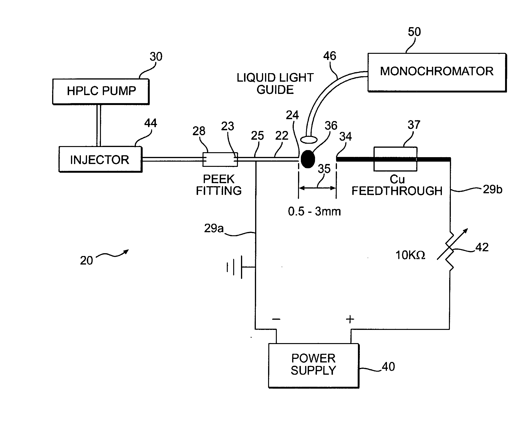
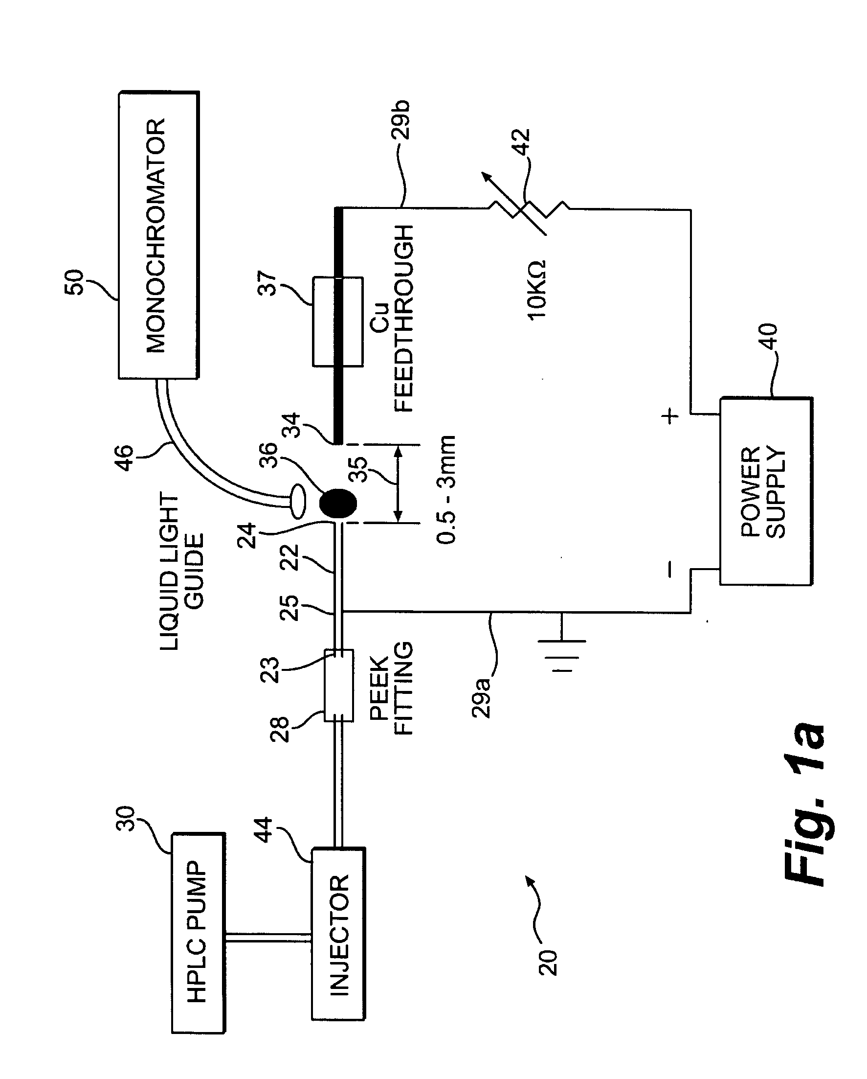
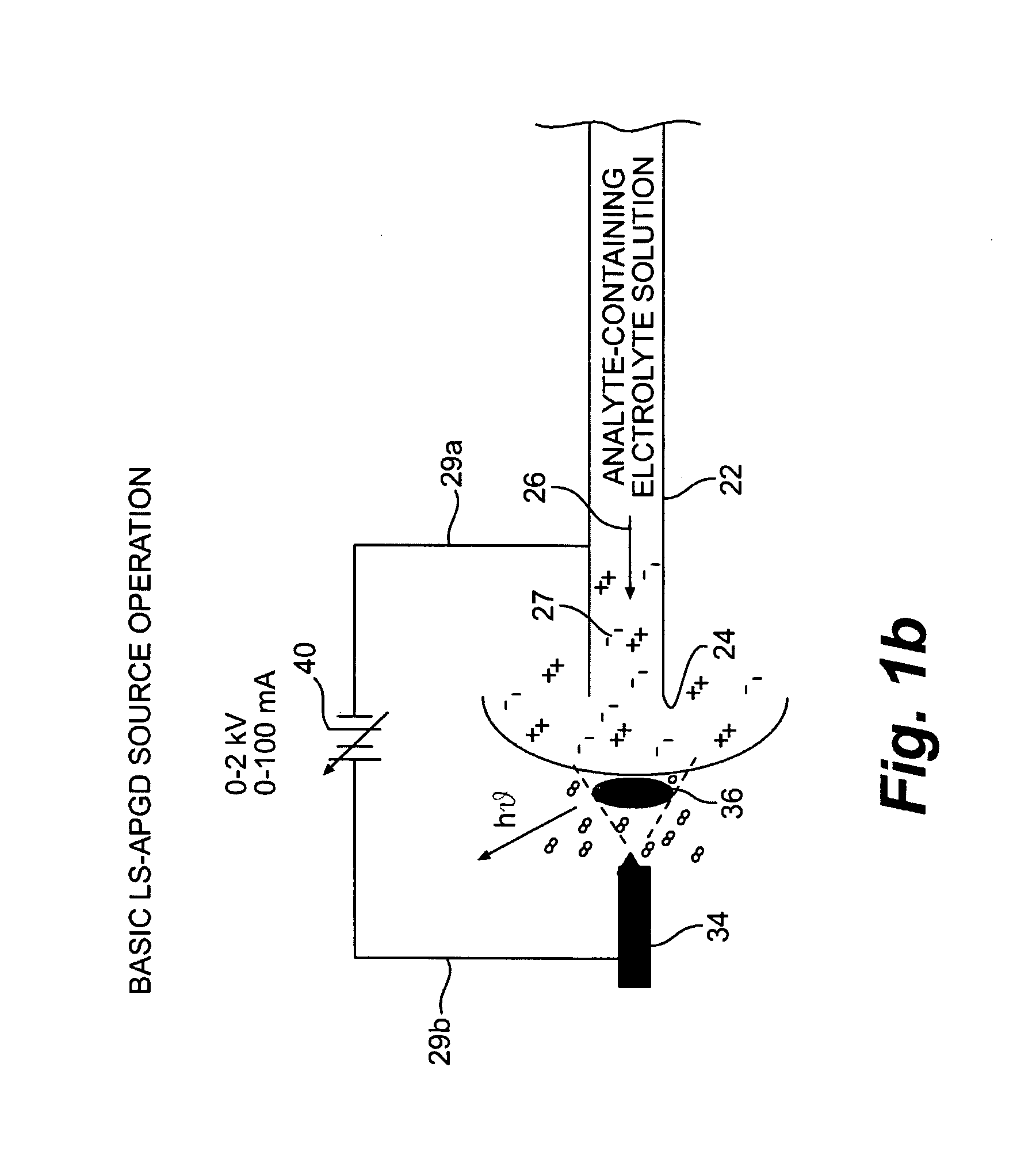
[0042] Reference now will be made in detail to the presently preferred embodiments of the invention, one or more examples of which are illustrated in the accompanying drawings. Each example is provided by way of explanation of the invention, not limitation of the invention. In fact, it will be apparent to those skilled in the art that various modifications and variations can be made in the present invention without departing from the scope or spirit of the invention. For instance, features illustrated or described as part of one embodiment, can be used on another embodiment to yield a still further embodiment. Thus, it is intended that the present invention cover such modifications and variations as come within the scope of the appended claims and their equivalents. The same numerals are assigned to the same components throughout the drawings and description.

[0043] A presently preferred embodiment of the liquid sampling-atmospheric pressure glow discharge (LS-APGD) apparatus of the...


PUM

PropertyMeasurementUnit
atmospheric pressureaaaaaaaaaa
diameteraaaaaaaaaa
flow rateaaaaaaaaaa

Abstract

A glow discharge optical emission spectroscopy (GD-OES) source operates at atmospheric pressure. One of the discharge electrodes of the device is formed by an electrolytic solution 27 containing the analyte specimen. The passage of electrical current (either electrons or positive ions) across the solution / gas phase interface causes local heating and the volatilization of the analyte species. Collisions in the discharge region immediately above the surface of the solution results in optical emission that is characteristic of the analyte elements. The device uses the analyte solution as either the cathode or anode. Operating parameters depend on the electrolyte concentration (i.e. solution conductivity) and the gap 35 between the solution surface and the counter electrode. Typical conditions include discharge currents of about 30 to about 60 mA and potentials of about 200 to about 1000 volts. Electrolyte solutions of pH, pNa or pLi values of about 0.5 to about 2 and interelectrode gaps of about 0.5 to about 3 mm produce stable plasmas where the analyte solutions are totally consumed at flow rates of up to about 2.0 mL / min.

Description

CROSS-REFERENCE TO RELATED APPLICATIONS [0001] This application claims priority to PCT International Application Serial No. PCT / US02 / 01523 filed Jan. 17, 2002.FEDERALLY SPONSORED RESEARCH [0002] Not-applicable. BACKGROUND OF THE INVENTION [0003] The present invention relates to spectrochemical sources and more particularly to glow discharge sources. [0004] Glow discharge (GD) plasmas have been used as spectrochemical (i.e., optical emission) sources for well over 100 years, dating back to the early studies of atomic structure. The low pressure, low power plasmas are easily controlled and yield emission spectra that are principally atomic in nature. The combination of cathodic sputtering as a means of introducing atoms from bulk solids and the relatively simple optical spectra lead to the implementation of hollow cathode GD devices as line sources for atomic absorption spectrophotometry. The development of the Grimm-type glow discharge geometry lead to the use of glow discharge optic...

Claims


Application Information

Patent Timeline
Patent Type & Authority Applications(United States)
IPC IPC(8): G01J3/10G01N21/67G01N21/69
CPCG01J3/10H01J49/00G01N21/69G01N21/67
Inventor MARCUS, R. KENNETHDAVIS, W. CLAY
Owner CLEMSON UNIVERSITY
Learn More