
Adjustable compensation of a piezo drive amplifier depending on mode and number of elements driven

Inactive Publication Date: 2005-01-20
TEXAS INSTR INC
View PDF13 Cites 11 Cited by
  • Summary
  • Abstract
  • Description
  • Claims
  • Application Information

AI Technical Summary

Benefits of technology

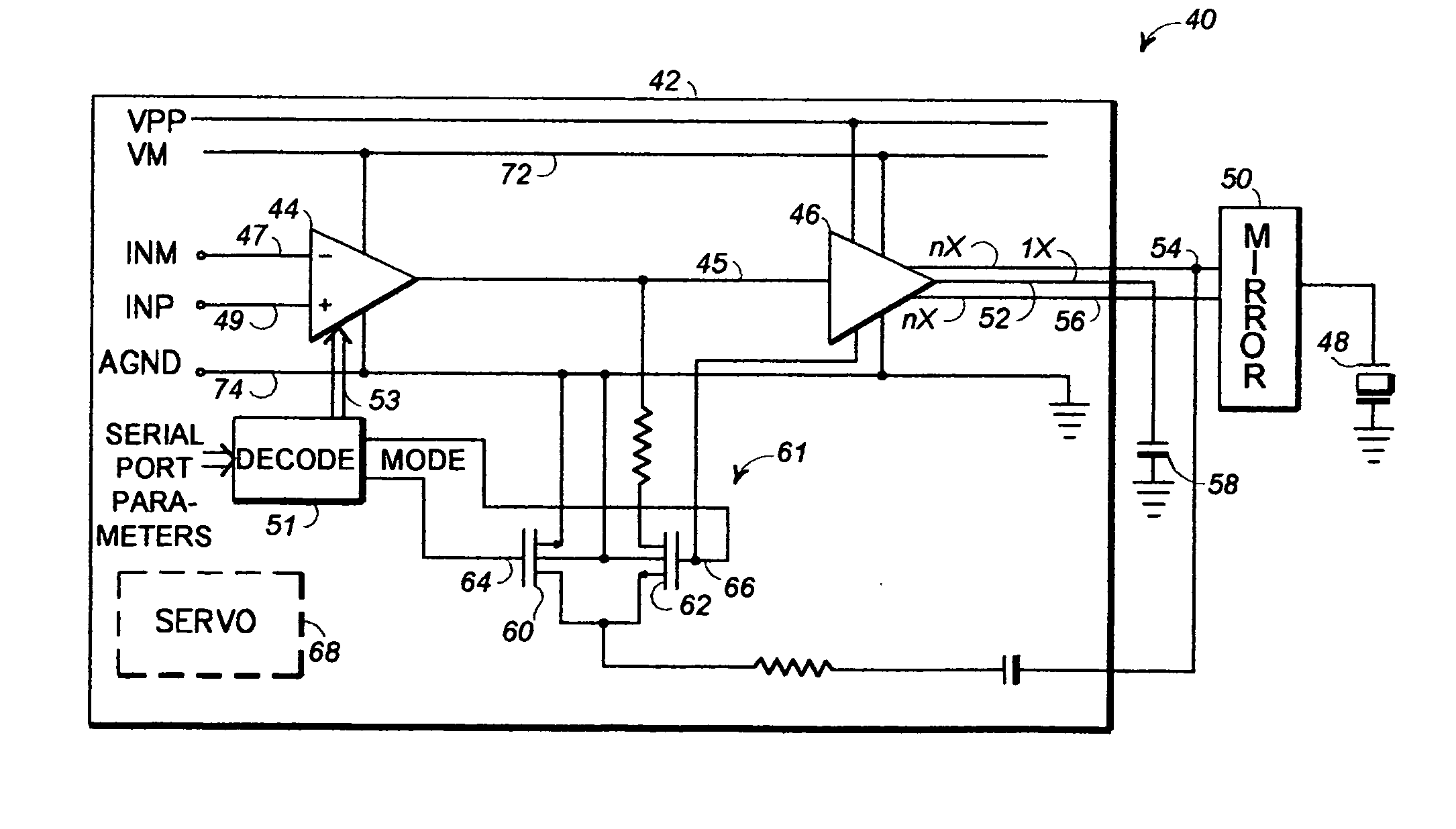
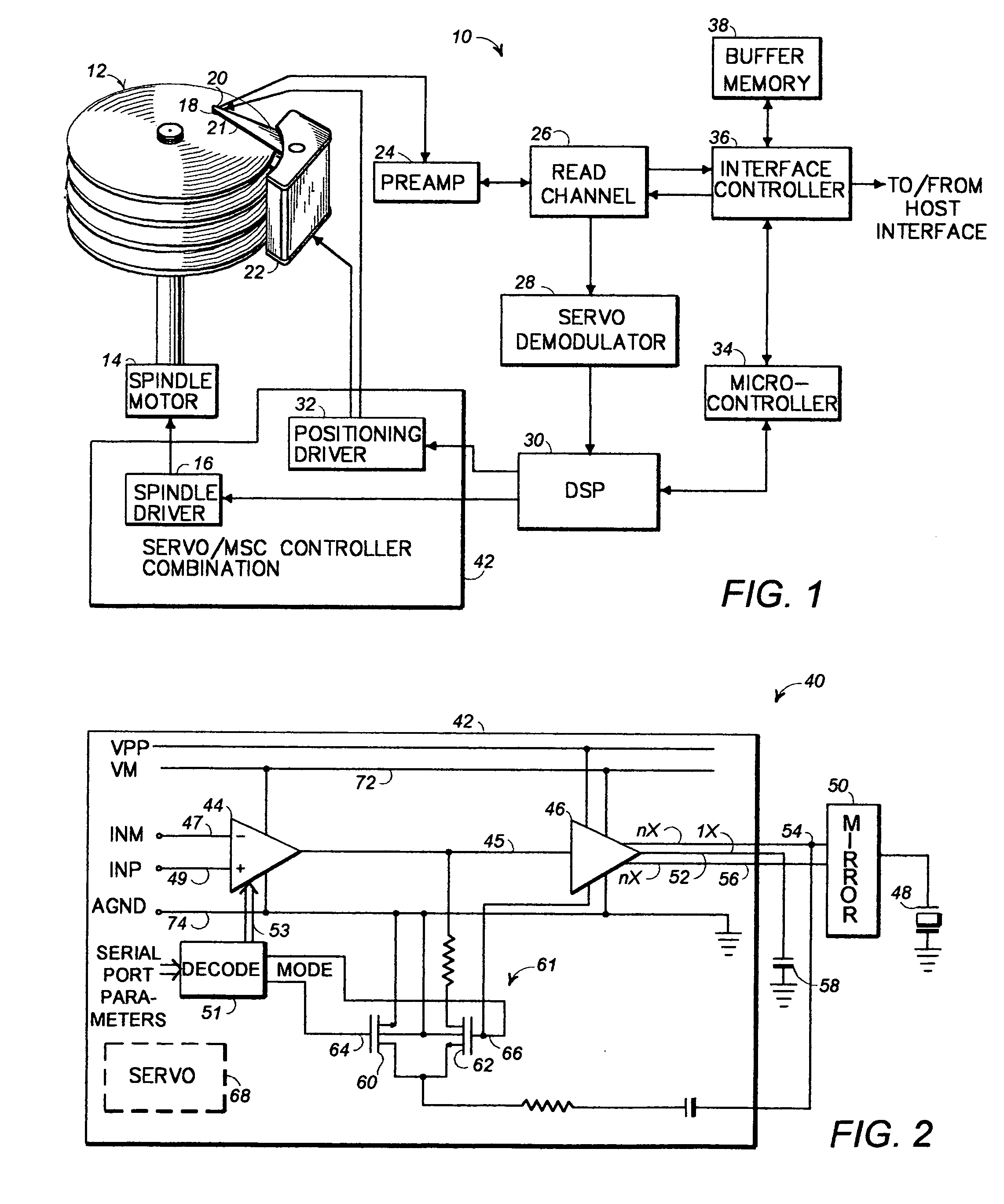
[0015] Thus, one of the advantages of the present invention is that a single amplifier serves both voltage mode and charge mode drive while also allowing for a varying number of elements to be driven in charge mode where the closed loop gain must change to adjust for the load changes. In all cases, a single amplifier can be allowed to serve these multiple purposes and remain stable.

Problems solved by technology

However, in the charge mode of operation, this feedback is not used and is switched to ground, and the amplifier is completely load compensated by the capacitor on the 1X output.

Method used


Image

  • Adjustable compensation of a piezo drive amplifier depending on mode and number of elements driven
  • Adjustable compensation of a piezo drive amplifier depending on mode and number of elements driven
  • Adjustable compensation of a piezo drive amplifier depending on mode and number of elements driven

Examples


Embodiment Construction

[0028]FIG. 1 is a block diagram of a generic disk drive system 10, which represents the general environment in which the invention may be practiced. The system 10 includes a magnetic media disk 12 that is rotated by a spindle motor 14 and spindle driver circuit 16. A data transducer or head 18 is locatable along selectable radial tracks (not shown) of the disk 12 by a voice coil motor 22, along a gross radial position. A milli-actuator 20 may be co-located with the head 18 on the end of the arm 21. The milli-actuator is preferably of the type that employs a piezo element for the fine positioning of the head 18, such devices being known in the art. (Although a piezo element type milli-actuator is preferably used, it should be understood that other types of milli-actuator devices may be equally advantageously employed.) The motion of the milli-actuator 20 may be a displacement to the left or right of the axis of the arm 21, to provide fine radial positioning of the head 18 along the t...


PUM


Abstract

An integrated circuit (42) provides drive signals to a piezo element (48) of a milli-actuator device (20) in a mass data storage device (10). The integrated circuit (42) includes a circuit (61) for selectively operating the integrated circuit (42) in either a voltage or a charge mode of operation. A first amplifier circuit (44) can be compensated for a variable number of piezo elements in the charge mode of operation by adjustable output impedance adjusting elements (124, 126, 138-141) that are switchably connectable into the amplifier circuit (44).

Description

CROSS REFERENCE TO RELATED APPLICATIONS [0001] This is a continuation-in-part of U.S. patent application Ser. No. 09 / 681,695 filed May 22, 2001 (Attorney docket number TI-31565).BACKGROUND OF INVENTION [0002] 1. Field of Invention [0003] This invention relates in part to improvements in methods and apparatuses for dynamic information storage or retrieval, and more particularly to improvements in methods and circuitry for positioning a transducer for writing or detecting data written onto a spinning data disk, and still more particularly to improvements in circuits for driving piezo-based milli-actuator structures and methods for making same. [0004] 2. Relevant Background [0005] Mass data storage devices include well known hard disk drives that have one or more spinning magnetic disks or platters onto which data is recorded for storage and subsequent retrieval. Hard disk drives may be used in many applications, including personal computers, set top boxes, video and television applica...

Claims


Application Information

Patent Timeline
Patent Type & Authority Applications(United States)
IPC IPC(8): H02N2/00H10N35/80H10N30/00H10N30/80
CPCH01L41/042H10N30/802
Inventor MURPHY, TERENCE J.
Owner TEXAS INSTR INC
Learn More