Fluorescent lamp electronic ballast

a technology of electronic ballast and fluorescent lamp, which is applied in the direction of electric variable regulation, process and machine control, instruments, etc., can solve the problems of inability to operate with a varying frequency, inability of conventional ballasts that use a hold-up capacitor or passive power factor correction (pfc) l-c filter on the input, and inability to control the output frequency of generated waveforms. , to achieve the effect of low in-rush current, wide frequency range operation

Inactive Publication Date: 2005-01-20
BRUCE AEROSPACE
View PDF8 Cites 12 Cited by
  • Summary
  • Abstract
  • Description
  • Claims
  • Application Information

AI Technical Summary

Benefits of technology

[0011] At a more detailed level, the present invention comprehends a PFC flyback topology capable of operation over a wide range of frequencies and having low in-rush current at turn on. The preferred PFC flyback circuit implementation has several aspects that make wide frequency range operation and low in-rush current at turn on possible. In the most preferred implementation, the PFC flyback circuit provides high power factor and low total harmonic distortion (THD) over a wide range of frequencies ranging from 60 Hz to 800 Hz. One aspect that serves to broaden the range of accommodated AC input frequencies received at the rectifier is that the rectifier has a sufficiently low input capacitance (preferably less than 0.5 microfarads) such that the rectifier output substantially takes the form of a rectified AC wave.
[0012] In preferred implementations, the flyback converter is configured to operate in a transition mode. That is, the switching frequency of the flyback transformer varies in response to the instantaneous line voltage and output current. Operating in transition mode is advantageous in that it results in reduced EMI when compared to a PFC circuit that has a fixed switching frequency. More preferably, the flyback converter includes a control loop configured to monitor the flyback transformer and switch the flyback transformer asynchronously as needed to maintain energy balance. That is, at high voltage input or low current output the energy drawn each cycle may exceed the short-term demand from the load and the control loop delays the turning on of the switch so as to maintain the long-term energy balance by switching asynchronously. Preferably, the control loop is connected to the DC output of the flyback circuit. Alternatively, a suitable arrangement could utilize an auxiliary winding to monitor the flyback transformer and switch asynchronously as needed to maintain energy balance.
[0013] Aspects that allow the flyback circuit to operate over a wide range of AC input frequencies including those exceeding 300 Hz and preferably those between 300 Hz and 800 Hz include the modification of design parameters as needed to accommodate the higher frequencies. In particular, higher frequencies are accommodated by reducing the value of the rectifier input capacitance, reducing a capacitance across an error amplifier for the control loop that monitors the flyback transformer to initiate asynchronous switching, and maintaining a ratio of a line input peak voltage to the reflected voltage of less than one by increasing the primary to secondary flyback transformer turns ratio. Further, it is preferred that a temperature compensating type capacitor be used for the error amplifier capacitor.
[0014] The PFC flyback circuit in the most preferred implementation converts wild frequency AC voltage to 28 VDC. The inverter ballast circuit preferably inverts the DC output to an AC signal and may be that described in U.S. Pat. No. 5,466,922. The PFC flyback stage improves line regulation as well as immunity from line transients, and reduces in-rush current at turn on.
[0015] An additional aspect of the preferred PFC flyback circuit is the ability to produce multiple DC output supplies. In a preferred implementation, the inverter ballast includes a self-oscillating resonant circuit including a pair of power transistors. The flyback converter is further used to create a DC bias for use by the power transistors. This technique reduces dissipated power in the bias supply when compared to traditional biasing techniques. Further, a similar approach may be utilized to supply power to arc detect and dim control circuitry when provided. It is appreciated that the flyback converter has a number of advantages in a lamp electronic ballast including the ability to regulate over a very wide variation in input voltage. Thus, for low line or high line conditions, the ballast light output remains unchanged. In addition, the preferred flyback circuit provides short circuit protection from gross output short circuit conditions.

Problems solved by technology

Wild frequency AC generators are not able to control the output frequency of the generated waveform.
However, conventional fluorescent lamp electronic ballasts are not able to accommodate the varying-frequency input.
Conventional ballasts that use a hold-up capacitor or passive power factor correction (PFC) L-C filters on the input are not able to operate with a varying frequency.
At higher frequencies, these conventional ballasts draw excessive current, exhibit poor power factor, and exhibit poor total harmonic distortion (THD).
Some background information may be found in ST Microelectronics application notes AN1059 “Design Equations Of High-Power-Factor Flyback Converters Based On The L6561,” AN1060 “Flyback Converters With The L6561 PFC Controller,” and AN1089 “Control Loop Modeling Of L6561-Based TM PFC.” However, these recent developments have only been discussed for certain specific 50 / 60 Hz applications and fail to discuss problems that arise with a wild frequency generator power source.

Method used


Image

  • Fluorescent lamp electronic ballast
  • Fluorescent lamp electronic ballast
  • Fluorescent lamp electronic ballast

Examples


Embodiment Construction

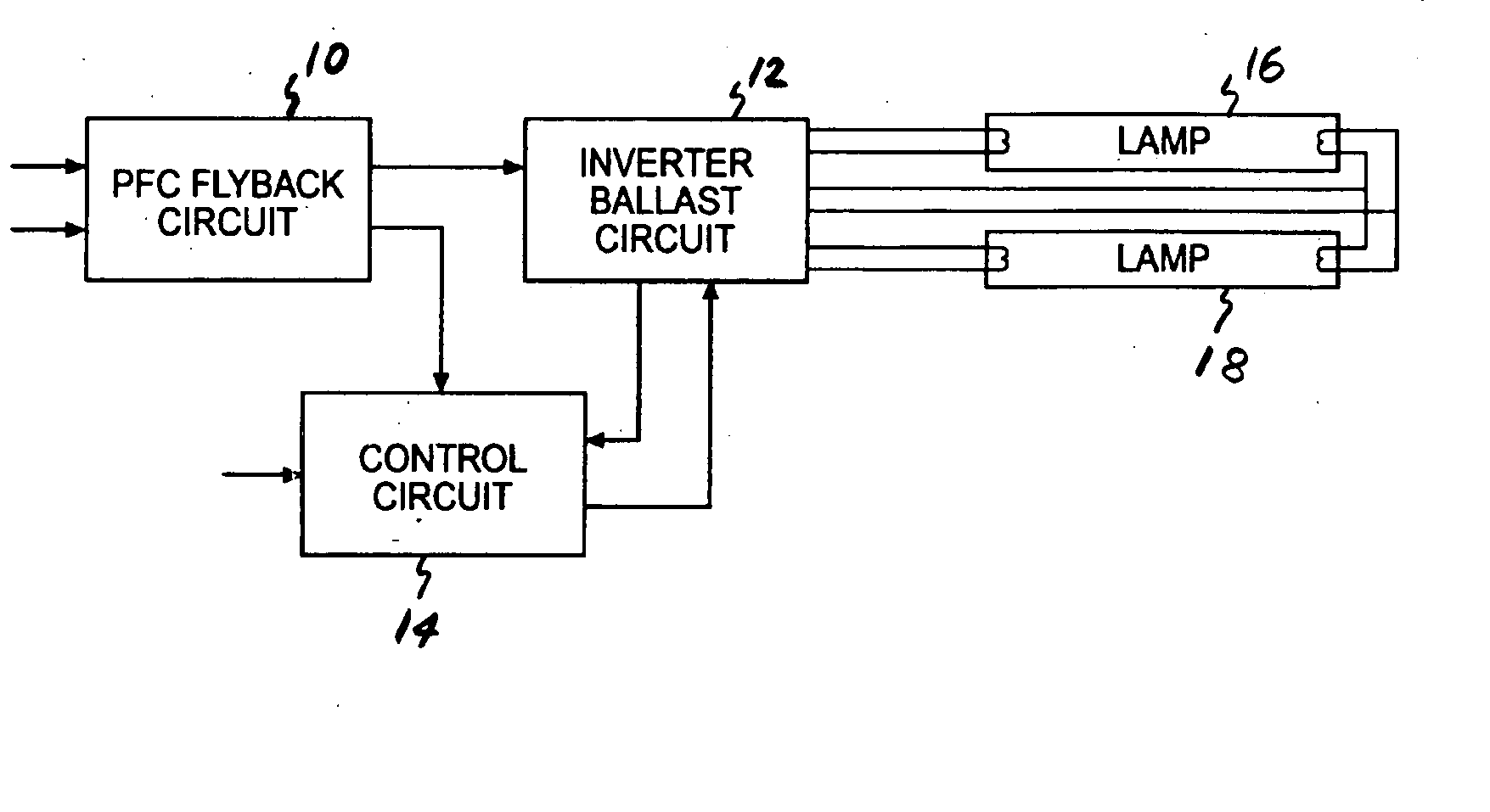
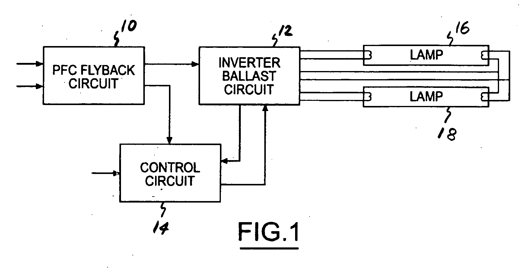
[0020]FIG. 1 illustrates a fluorescent lamp electronic ballast including a power factor correction (PFC) flyback circuit 10, inverter ballast circuit 12, and control circuit 14. PFC flyback circuit 10 is composed of a rectifier receiving an AC input signal with the rectifier being connected to a DC to DC flyback converter. Inverter ballast circuit 12 receives the DC output from PFC flyback circuit 10 and converts the DC output to an AC signal for operating one or more fluorescent lamps 16, 18. Control circuit 14 includes arc detect and dim control circuitry.

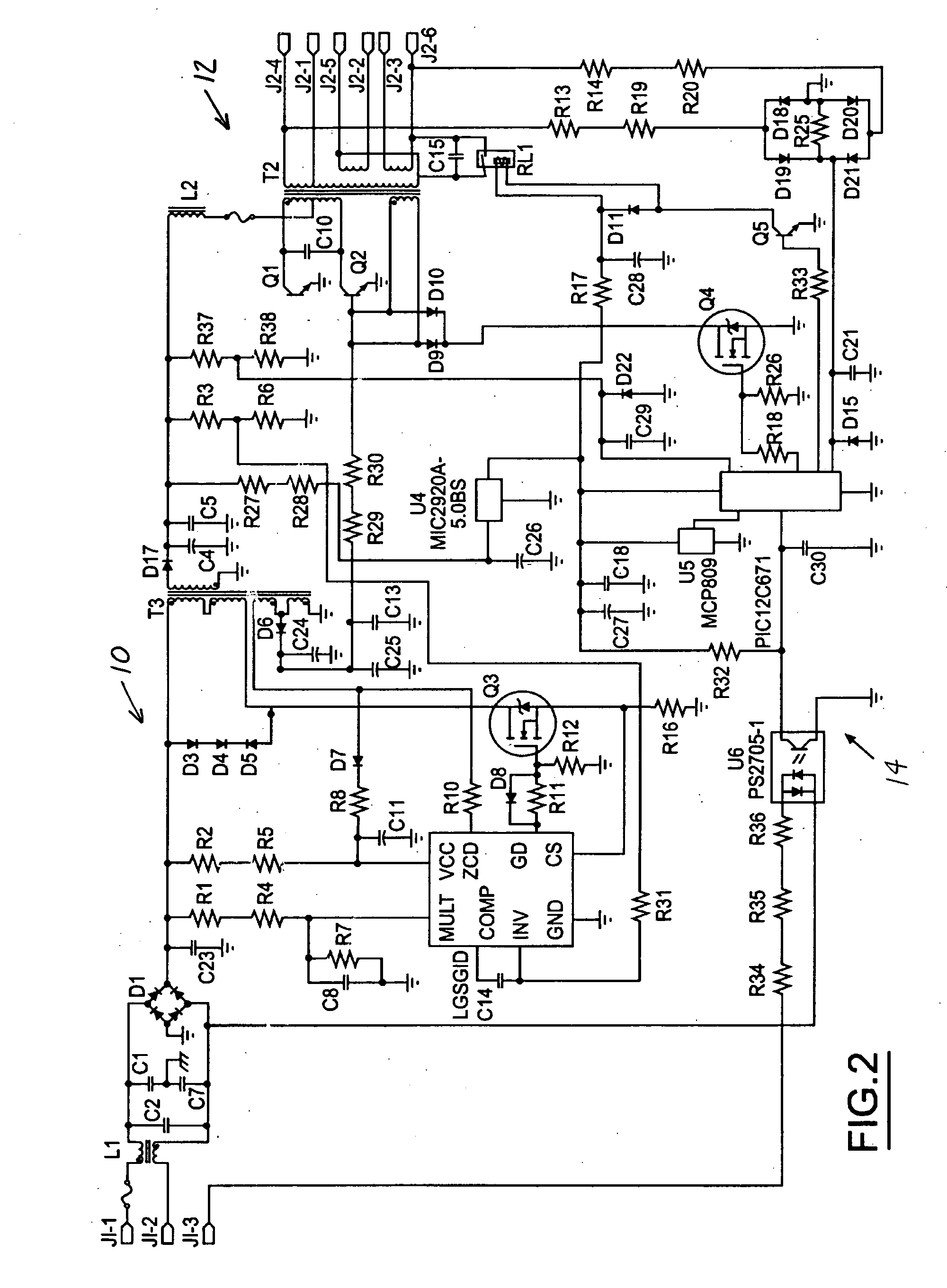
[0021]FIG. 2 illustrates the ballast components in greater detail. Referring to PFC flyback circuit 10, inputs J1-1 and J1-2 receive an AC voltage such as that generated by a wild frequency AC generator. EMI filtering is performed by inductors L1 and capacitors C1, C2, C7. Diode bridge D1 rectifies the input signal. One aspect that serves to broaden the range of accommodated AC input frequencies received at the rectifier is that...


PUM


Abstract

A fluorescent lamp electronic ballast includes a power factor correction flyback circuit and an inverter ballast circuit. The power factor correction flyback circuit is composed of a rectifier connected to a DC to DC flyback converter. The flyback converter includes a flyback transformer connected to a diode/capacitor combination. The flyback transformer is switched during operation to produce a flyback waveform that is rectified by the diode and results in a DC output at the capacitor. The inverter ballast circuit receives the DC output and converts the DC output to an AC signal for operating the flourescent lamp.

Description

BACKGROUND OF THE INVENTION [0001] 1. Field of the Invention [0002] The present invention relates to fluorescent lamp electronic ballasts and to power factor correction for fluorescent lamp electronic ballasts. [0003] 2. Background Art [0004] Fluorescent lamps with electronic ballasts are used in the aircraft industry because of the efficiency of fluorescent lighting technology. Conventional aircraft generators produce an AC voltage of nearly constant frequency. The conventional fluorescent lamp electronic ballast accommodates the nearly constant frequency AC voltage and drives one or more lamps with reasonable performance. [0005] Recently, aircraft manufacturers have begun to employ wild frequency generators. Wild frequency AC generators are not able to control the output frequency of the generated waveform. The output frequency of the generator varies with the engine speed of the aircraft, typically producing a waveform with frequencies between 300 Hz and 800 Hz. Due to the reduct...

Claims


Application Information

Patent Timeline
Patent Type & Authority Applications(United States)
IPC IPC(8): H05B41/282
CPCY02B20/183H05B41/282Y02B20/00
Inventor NEMIROW, ARTHUR T.PARK, CHARLIE C.
Owner BRUCE AEROSPACE
Why Eureka
Try Eureka