Check patentability & draft patents in minutes with Patsnap Eureka AI!

Gamma correction circuit, liquid crystal driving circuit, display and power supply circuit

Inactive Publication Date: 2005-01-20
SEIKO EPSON CORP
View PDF8 Cites 26 Cited by
  • Summary
  • Abstract
  • Description
  • Claims
  • Application Information

AI Technical Summary

Benefits of technology

[0048] Accordingly, oscillation of the operational amplifier is prevented such that the stable gray scale voltage can be supplied. In addition, power consumption can be suppressed.
[0050] Since the gamma correction curve around the intermediate gray scale voltage is more linear (straight line manner) compared to that around the edge gray scale voltage (in the vicinity of input voltage), only the resistors around edge gray scale voltage (in the vicinity of input voltage) are variable resistors. Only the setting of the gray scale voltage that is a non-linear part is changed corresponding to a new gamma characteristic, and thereby the setting of a gray scale voltage that is a linear part is also changed along with the new gamma characteristic. Namely, the ratio of gamma correction resistance around the intermediate gray scale, where a gamma characteristic is linear, need not be changed. In this case, the circuit arrangement can be simplified compared to the case where all of the gamma correction resistors are variable resistors. Accordingly, a cost burden and labor burden of manufacturing can be reduced.

Problems solved by technology

Thus, although the structure is simple, cross talk due to leakage of charges from the adjacent pixels is caused, and there is a limitation in increasing resolution and data amount of display.
In addition, with respect to gray scale control in a passive matrix liquid crystal display, gray scale control by each pixel is difficult because of the structure thereof.
These methods, however, are not suitable for increasing resolution and gray scale of display images.
Namely, in the case where the same gamma correction circuit is used for a liquid crystal display having a different gamma characteristic, the ratio of gamma correction resistance on an input side needs be changed for the difference in a gamma characteristic and thus causing a problem that a current is generated between the gamma correction resistor and the operational amplifier.
Furthermore, in the case where a potential difference is caused between the node of the gamma correction resistor on an input side and the node of the corresponding gamma correction resistor on an output side such that a current is generated between the gamma correction resistor on an output side and the operational amplifier, there is a problem that a stable gray scale voltage can not be supplied since the operational amplifier may oscillate.
There is also a problem that power consumption is increased because of overcurrent.
For example, in the case of a liquid crystal display driven with a battery, there is a problem that driving time (time when display is possible) becomes short.
In recent years, there has been a trend where current consumption in a driver IC for driving a liquid crystal display increases as a display capacity of a liquid crystal display increases.
However, the increase in current consumption is not allowed even if display capacity is increased.

Method used


Image

  • Gamma correction circuit, liquid crystal driving circuit, display and power supply circuit
  • Gamma correction circuit, liquid crystal driving circuit, display and power supply circuit
  • Gamma correction circuit, liquid crystal driving circuit, display and power supply circuit

Examples


Embodiment Construction

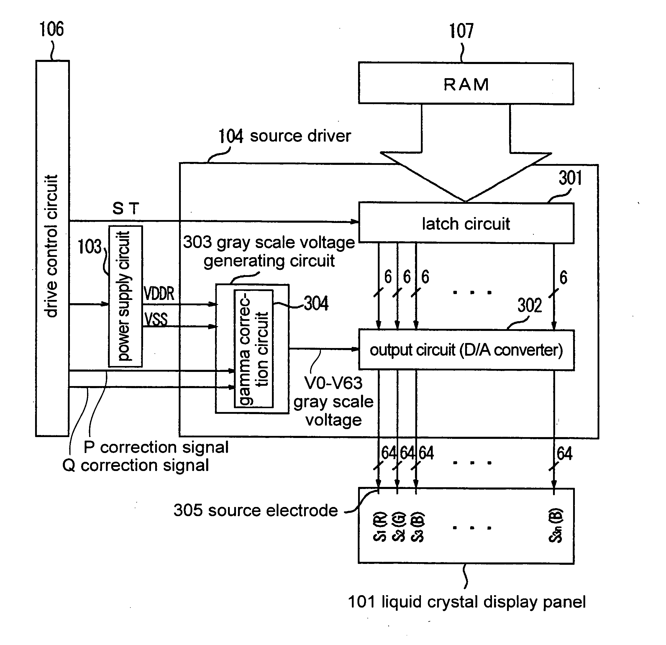
[0077] Preferred embodiments of a gamma correction circuit according to the present invention will be described below in detail with reference to accompanying drawings. In the following description and accompanying drawings, the same numerals are given to structural elements having substantially the same function and structure and overlapping explanation will be omitted.

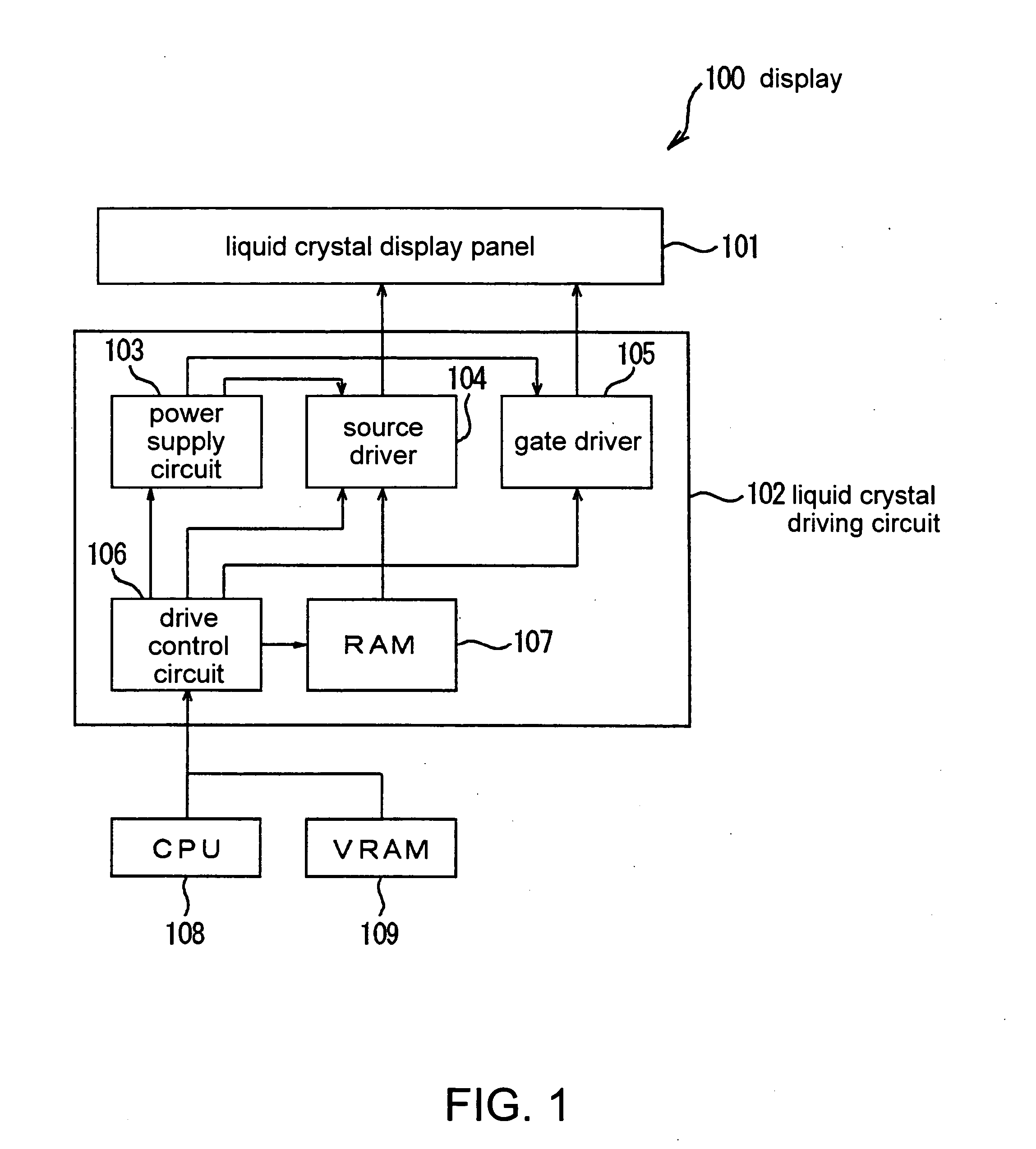
[0078] First, the schematic structure of a display for which a gamma correction circuit is provided will be described with reference to FIG. 1.

[0079]FIG. 1 is a diagram schematically showing the structure of a display 100 for which a gamma correction circuit is provided.

[0080] The display 100 comprises a liquid crystal display panel 101 and a liquid crystal driving circuit 102. The devices are coupled to each other with a system bus.

[0081] The display 100 is coupled to a CPU 108 and a VRAM 109 (Video RAM) with a system bus, various cables, wireless communication, and so on.

[0082] The liquid crystal display panel...


PUM


Abstract

A gamma correction circuit is provided. Gamma correction resistors on an input side are coupled to each other in series between input voltages. The gamma correction resistors around the input voltages are variable resistors and the other resistors are fixed resistors. Gamma correction resistors on an output side are coupled to each other in series between the input voltages. The gamma correction resistors in the vicinity of the input voltages are variable resistors and the other resistors are fixed resistors. When the setting of gray scale voltages is changed by changing the gamma correction resistors on the input side, the gamma correction resistors on the output side are simultaneously changed. Thereby, the potentials of an input side and output side of an operational amplifier are kept identical to each other such that overcurrent does not flow between the gamma correction resistor and the operational amplifier.

Description

RELATED APPLICATIONS [0001] This application claims priority to Japanese Patent Application No. 2003-172104 filed Jun. 17, 2003 which is hereby expressly incorporated by reference herein in its entirety. BACKGROUND [0002] 1. Field of the Invention [0003] The present invention relates to a gamma correction circuit in a display. More specifically, the invention relates to a gamma correction circuit (y correction circuit) producing gray scale voltage corresponding to the gamma characteristic of a display. [0004] 2. Description of Related Art [0005] In recent years, as displays such as a liquid crystal display and a CRT display spread, the displays are required to have further improved display quality, a higher resolution, and a larger capacity. [0006] Generally, displays such as a liquid crystal display and a CRT display each have a specific gamma characteristic such that inputs (input voltage, an input signal, etc.) and outputs (gray scale, optical transparency, brightness, etc.) do n...

Claims


Application Information

Patent Timeline
IPC IPC(8): G02F1/01G09G3/00G09G3/20G09G3/36H04N5/00H04N5/202H04N5/66H04N9/00
CPCG09G3/3688G09G2330/02G09G2320/0276G09G3/3696
Inventor HARA, TARO
Owner SEIKO EPSON CORP
Features
  • R&D
  • Intellectual Property
  • Life Sciences
  • Materials
  • Tech Scout
  • Unparalleled Data Quality
  • Higher Quality Content
  • 60% Fewer Hallucinations
Learn More