Scanning laser microscope
a laser microscope and scanning laser technology, applied in the field of scanning laser microscopes, can solve problems such as differences in response tim
- Summary
- Abstract
- Description
- Claims
- Application Information
AI Technical Summary
Benefits of technology
Problems solved by technology
Method used
Image
Examples
first embodiment
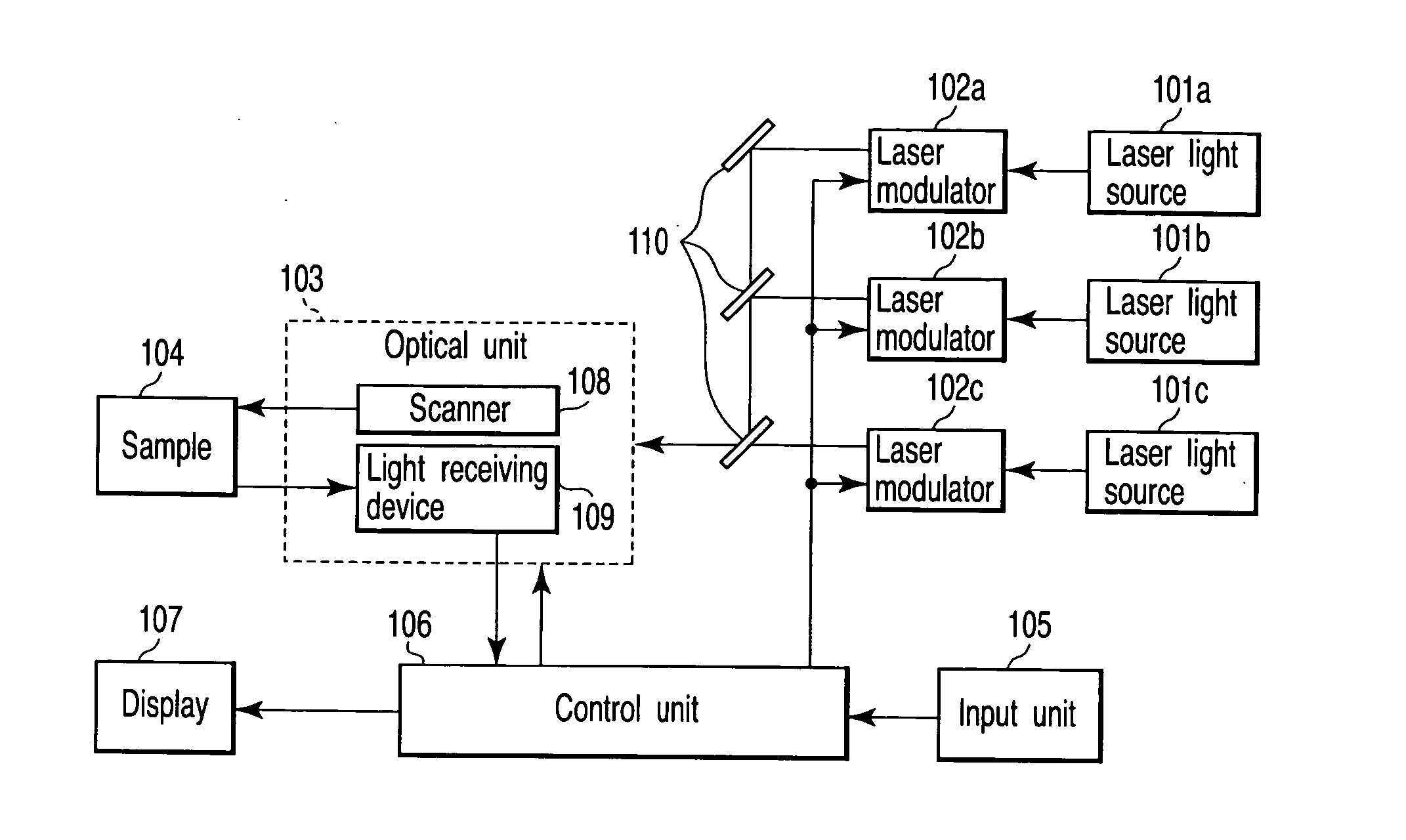
[0025]FIG. 1 is a diagram showing a configuration of a scanning laser microscope according to the present invention. The scanning laser microscope includes a plurality of types of acoustooptic devices for changing a quantity and wavelength of excitation light.
[0026] Each of a plurality of laser light sources (laser light irradiation means) 101a, 101b, 101c is a light source for excitation. Laser light (laser beam) emitted from each laser light source 101a, 101b, 101c individually enters one of a plurality of laser modulators 102a, 102b, 102c. Each laser modulator 102a, 102b, 102c can change at least one of a wavelength and quantity (intensity) of laser light irradiated to a sample in accordance with the scanning position of laser light. Each laser modulator 102a, 102b, 102c is, for example, configured with an acoustooptic device (AOTF), a combination of a shutter and a filter, or the like.
[0027] The laser lights emitted from the respective laser modulators 102a, 102b, 102c are comb...
second embodiment
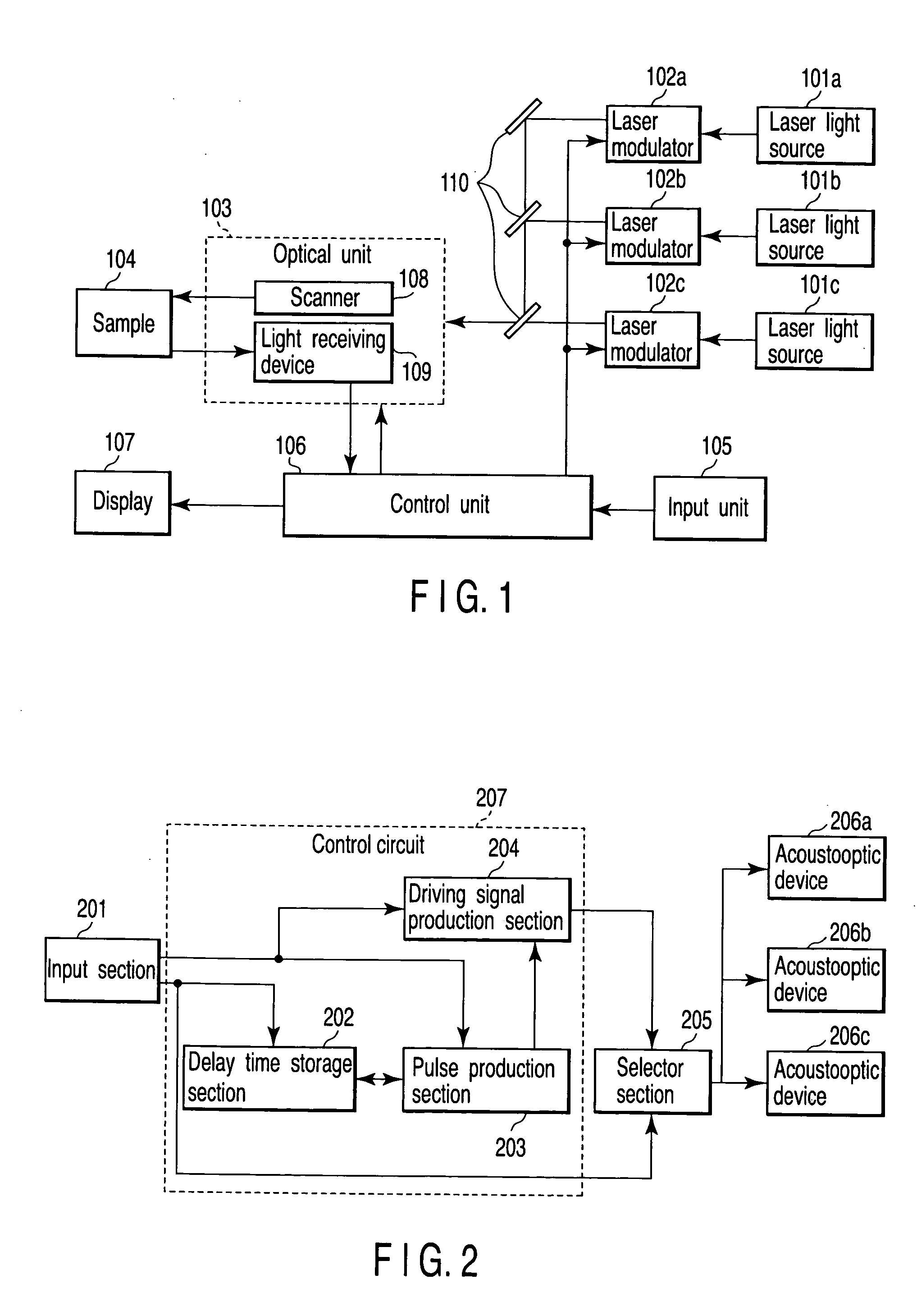
[0049]FIG. 6 is a diagram showing a configuration of a 20 part of the scanning laser microscope in detail. In FIG. 6, acoustooptic devices 406a, 406b, 406c are driven by a driving signal produced in response to an input signal.
[0050] A configuration of FIG. 6 is configured with an input section 401, a selector section 402, a plurality of control circuits 407a 407b, 407c, and a plurality of acoustooptic devices 406a, 406b, 406c. Each of the control circuits 407a 407b, 407c corresponds to each acoustooptic device 406a 406b, 406c. Each control circuit 407a 407b, 407c is configured with a delay time storage section 403, a pulse production section 404, and a driving signal production section 405. The delay time storage section 403, pulse production section 404, driving signal production section 405, and selector section 402 are included in the control unit 106 of FIG. 1.
[0051] In the input section 401, the user inputs laser irradiation range data indicating a laser irradiation range, a...
fourth embodiment
[0067]FIG. 8 is a diagram showing a configuration of a part of the scanning laser microscope according to the In FIG. 8, the acoustooptic device is driven by a driving signal produced in response to an input signal.
[0068] A configuration of FIG. 8 is configured with an input section 501, a control circuit A 512, a plurality of control circuits B 513a, 513b, a selector section 505, a reference acoustooptic device 510, and a plurality of acoustooptic devices 511a, 511b. The control circuit A 512 is constituted of a delay time storage section 502, a pulse production section 503, and a driving signal production section 504. Each of the control circuits B 513a, 513b is constituted of an A / D conversion section 506, an FIFO memory 507, a difference delay time storage section 508, and a D / A conversion section 509. The delay time storage section 502, pulse production section 503, and driving signal production section 504 of the control circuit A 512 are included in the control unit 106 of F...
PUM
 Abstract
Description
Claims
Application Information
 - R&D
- Intellectual Property
- Life Sciences
- Materials
- Tech Scout
- Unparalleled Data Quality
- Higher Quality Content
- 60% Fewer Hallucinations
Browse by: Latest US Patents, China's latest patents, Technical Efficacy Thesaurus, Application Domain, Technology Topic, Popular Technical Reports.
© 2025 PatSnap. All rights reserved.Legal|Privacy policy|Modern Slavery Act Transparency Statement|Sitemap|About US| Contact US: help@patsnap.com


