Apparatus for producing hydrogen

Inactive Publication Date: 2005-01-20
MITSUBISHI HEAVY IND LTD
View PDF10 Cites 7 Cited by
  • Summary
  • Abstract
  • Description
  • Claims
  • Application Information

AI Technical Summary

Benefits of technology

[0011] The present invention has been accomplished in light of these circumstances. It is an object of this invention to actualize such a concrete and feasible apparatus layout involving a pressure reducing device and provide an apparatus for producing hydrogen with the use a hydrogen separation type reformer, the apparatus having a minimal area required, and having improved durability while using a pressure reducing device.

Problems solved by technology

However, such a rotary device has difficulty in efficiently delivering a light gas, such as hydrogen, thus requiring a high power.
Furthermore, the aforementioned Japanese Unexamined Patent Publication No. 4-325402 does not propose a concrete apparatus layout including a pressure reducing device, and cannot actualize a feasible apparatus.

Method used


Image

  • Apparatus for producing hydrogen
  • Apparatus for producing hydrogen
  • Apparatus for producing hydrogen

Examples


example 1

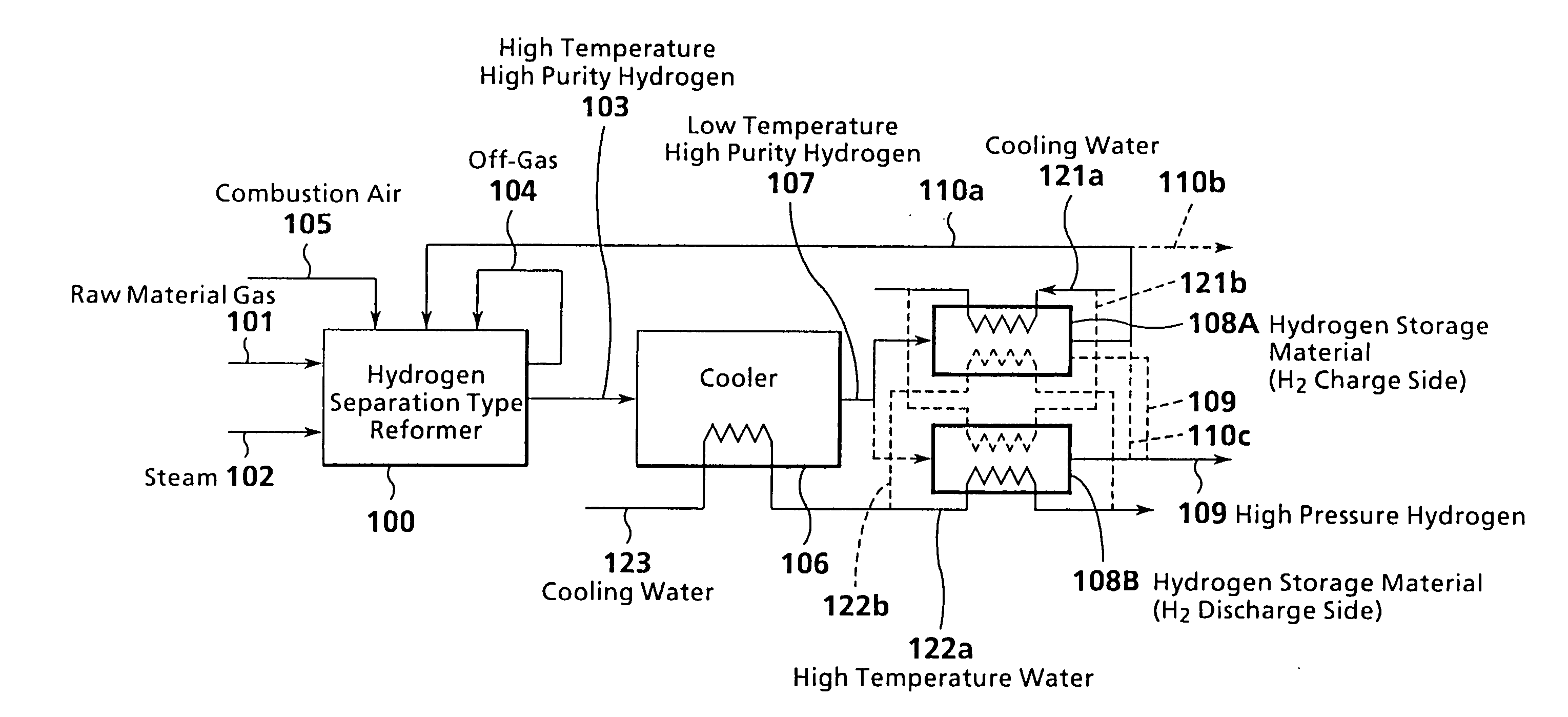
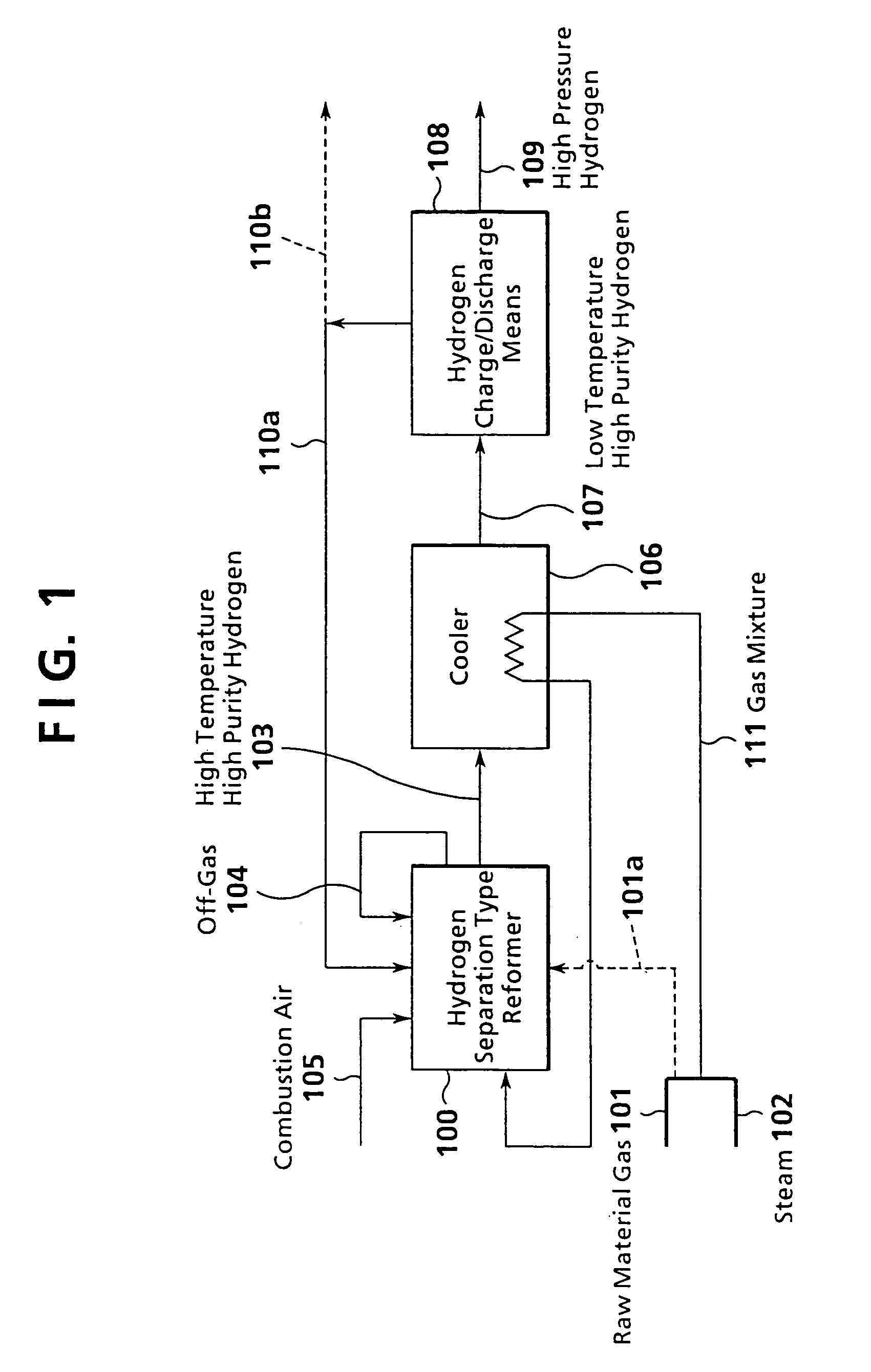
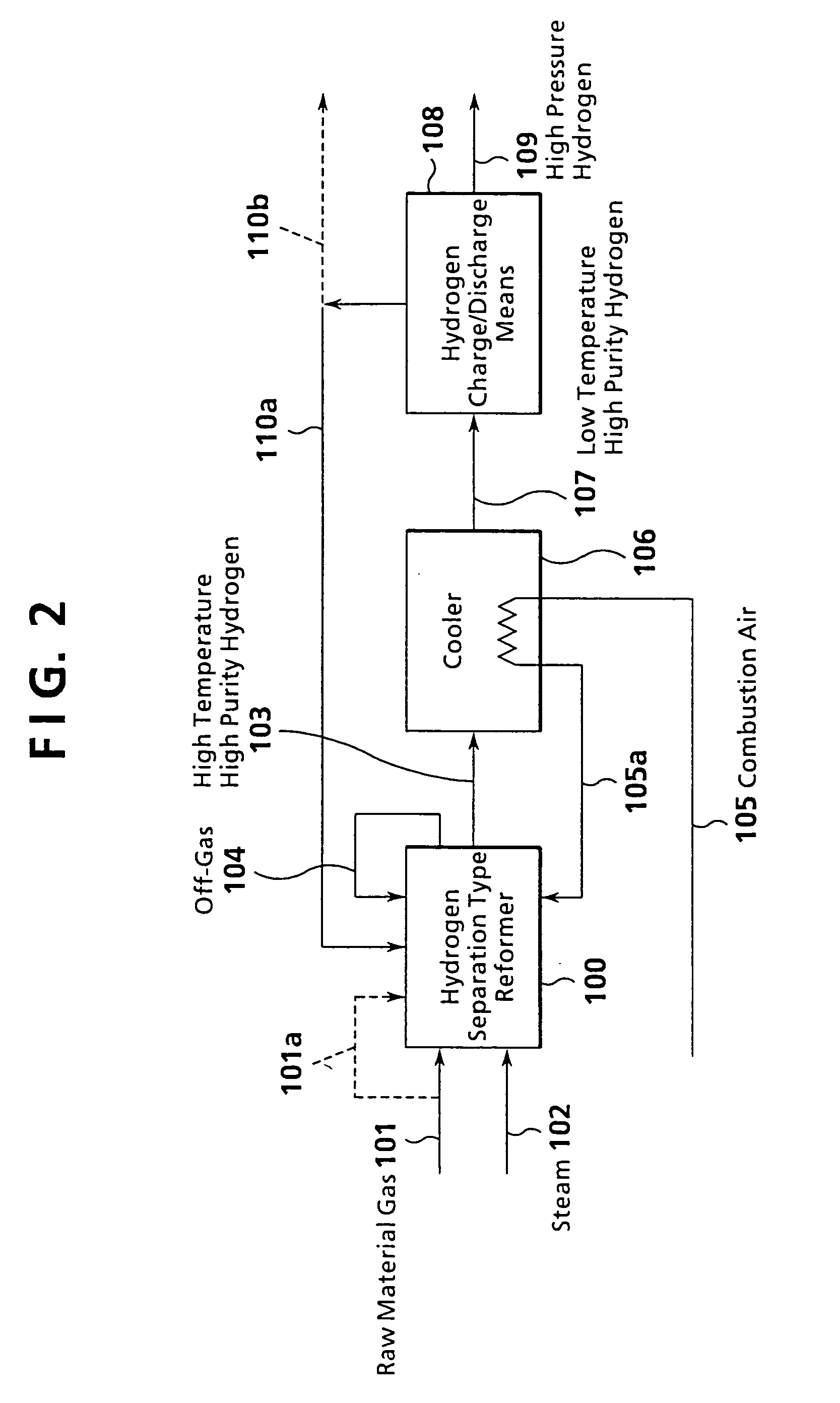
[0070] A first example of the invention will be explained based on the apparatus layout shown in FIG. 3. A hydrogen separation type reformer 100 had the structure shown in FIGS. 7 and 8, as with the preceding Embodiments. A heat exchanger, a cooler 106, was of a plate fin type, and used cooling water as a low temperature fluid 120a to cool high temperature high purity hydrogen 103. A hydrogen occluding material of a hydrogen storage / delivery means 108 was composed of two members of a hydrogen storing alloy of LaNi5.

[0071] Hydrogen was produced under the following concrete conditions in accordance with the flow shown in FIG. 3.

[0072] (1) Hydrogen Separation Type Reformer (100)

[0073] Main Constitution

[0074] The catalyst of the reformer 100 was an NiO catalyst in particle form, and the hydrogen separation membrane was made of a Pd alloy. The membrane area was 0.68 cm2.

[0075] Operating Conditions

[0076] The reaction temperature of the reformer was 550° C., and the reaction pressure...

example 2

[0085] A second example of the invention will be explained based on the apparatus layout shown in FIG. 3.

[0086] (1) Hydrogen Separation Type Reformer (100)

[0087] The constitution and operating conditions were the same as in Example 1.

[0088] (2) Cooler (106)

[0089] The same constitution and operating conditions as in Example 1 were adopted, except that the outlet temperature of low temperature high purity hydrogen 107 in the cooler 106 was 80° C.

[0090] (3) Hydrogen Storing Alloy

[0091] The same constitution and operating conditions as in Example 1 were adopted.

[0092] (4) Amount of Hydrogen Production

[0093] When the high purity hydrogen outlet temperature was 40° C. as in Example 1, the amount of hydrogen production was 3.0 m3 N / h. When the high purity hydrogen outlet temperature was 80° C., on the other hand, the amount of hydrogen production was 2.0 m3 N / h.

example 3

[0094] A third example of the invention will be explained based on the apparatus layout shown in FIG. 5.

[0095] A hydrogen separation type reformer 100, a cooler 106, and a hydrogen storage / delivery means 108 had the same constitutions as in Example 1. A pressure regulator 130 comprises a pressure regulating valve, and mitigates a rapid pressure fall at the start of hydrogen occlusion by the hydrogen storage / delivery means 108. Thus, the pressure regulator 130 curbs a rapid pressure change of low temperature high purity hydrogen 107 flowing out of the cooler 106.

[0096] Hydrogen was produced under the following concrete conditions:

[0097] The constitutions and operating conditions of the hydrogen separation type reformer 100, cooler 106, and hydrogen storage / delivery means 108 were the same as in Example 1.

[0098]FIG. 6 shows changes in the pressure of low temperature high purity hydrogen during hydrogen occlusion. Regulation of the pressure results in the mitigation of a rapid pres...


PUM

PropertyMeasurementUnit
Temperatureaaaaaaaaaa
Pressureaaaaaaaaaa

Abstract

An apparatus for producing hydrogen by a steam reforming reaction, on a catalyst, of a hydrocarbon or an oxygen-containing hydrocarbon as a raw material is disclosed. The apparatus comprises a hydrogen separation type reformer which has a means for heating the catalyst and which has a hydrogen separation membrane built into a layer of the catalyst for selectively separating hydrogen; a cooling means for cooling high temperature high purity hydrogen obtained from the reformer; and a hydrogen storage / delivery means disposed downstream from the cooling means and composed of a hydrogen occluding material.

Description

BACKGROUND OF THE INVENTION [0001] 1. Field of the Invention [0002] The present invention relates to an apparatus for producing hydrogen by a steam reforming reaction using a hydrocarbon or an oxygen-containing hydrocarbon as a raw material. [0003] 2. Description of the Related Art [0004] A conventional apparatus for producing hydrogen with the use of a hydrogen separation type reformer is proposed, for example, in Japanese Unexamined Patent Publication No. 4-325402. Disclosed in this proposal is an apparatus for producing hydrogen for a fuel cell with the use of a hydrogen separation type reformer from which hydrogen is withdrawn by a pressure reducing means. The concept of constitution of this apparatus is illustrated in FIG. 9. [0005] As shown in FIG. 9, a hydrogen separation membrane 02 and a catalyst 08 are provided in a hydrogen separation type reformer 01. A gas as a raw material (hereinafter referred to as a raw material gas) 06 and steam 07 are fed to the hydrogen separatio...

Claims


Application Information

Patent Timeline
IPC IPC(8): B01D53/22C01B3/00C01B3/32C01B3/38C01B3/50C22C14/00H01M8/06
CPCB01D53/229Y02E60/327C01B3/323C01B3/38C01B3/501C01B2203/0233C01B2203/041C01B2203/047C01B2203/0475C01B2203/0811C01B2203/0816C01B2203/0822C01B2203/0844C01B2203/0866C01B2203/0883C01B2203/1011C01B2203/1052C01B2203/1223C01B2203/1241C01B2203/148C01B2203/1633C01B2203/82C01B3/0005Y02E60/32Y02P20/10Y02P30/00
Inventor KOBAYASHI, KAZUTOFUJIMOTO, YOSHIMASA
Owner MITSUBISHI HEAVY IND LTD
Why Eureka
Try Eureka