Real-time implementation of field programmable gate arrays (FPGA) design in hyperspectral imaging
a hyperspectral imaging and field programmable gate array technology, applied in image enhancement, scene recognition, instruments, etc., can solve the problems of reducing the payload of aircraft and satellites, limiting the applicability of real-time processing problems, and largely absent science data processing on board remote sensing missions
- Summary
- Abstract
- Description
- Claims
- Application Information
AI Technical Summary
Benefits of technology
Problems solved by technology
Method used
Image
Examples
first embodiment
In the invention for CEM implementation, Eq. (5) is decomposed into several components, each component implemented by a separated hardware module, whereby w*=RL×L-1ddTRL×L-1d=(XXT)-1ddT(XXT)-1d=(Rtupper)-1[(Rtupper)T]-1ddT(Rtupper)-1[(Rtupper)T]-1d.(11)
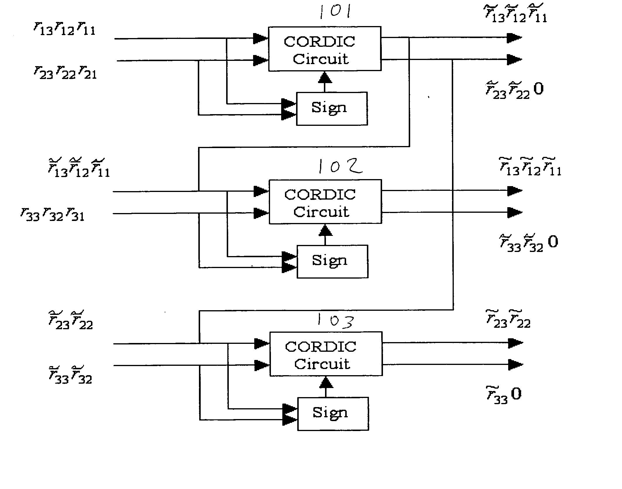
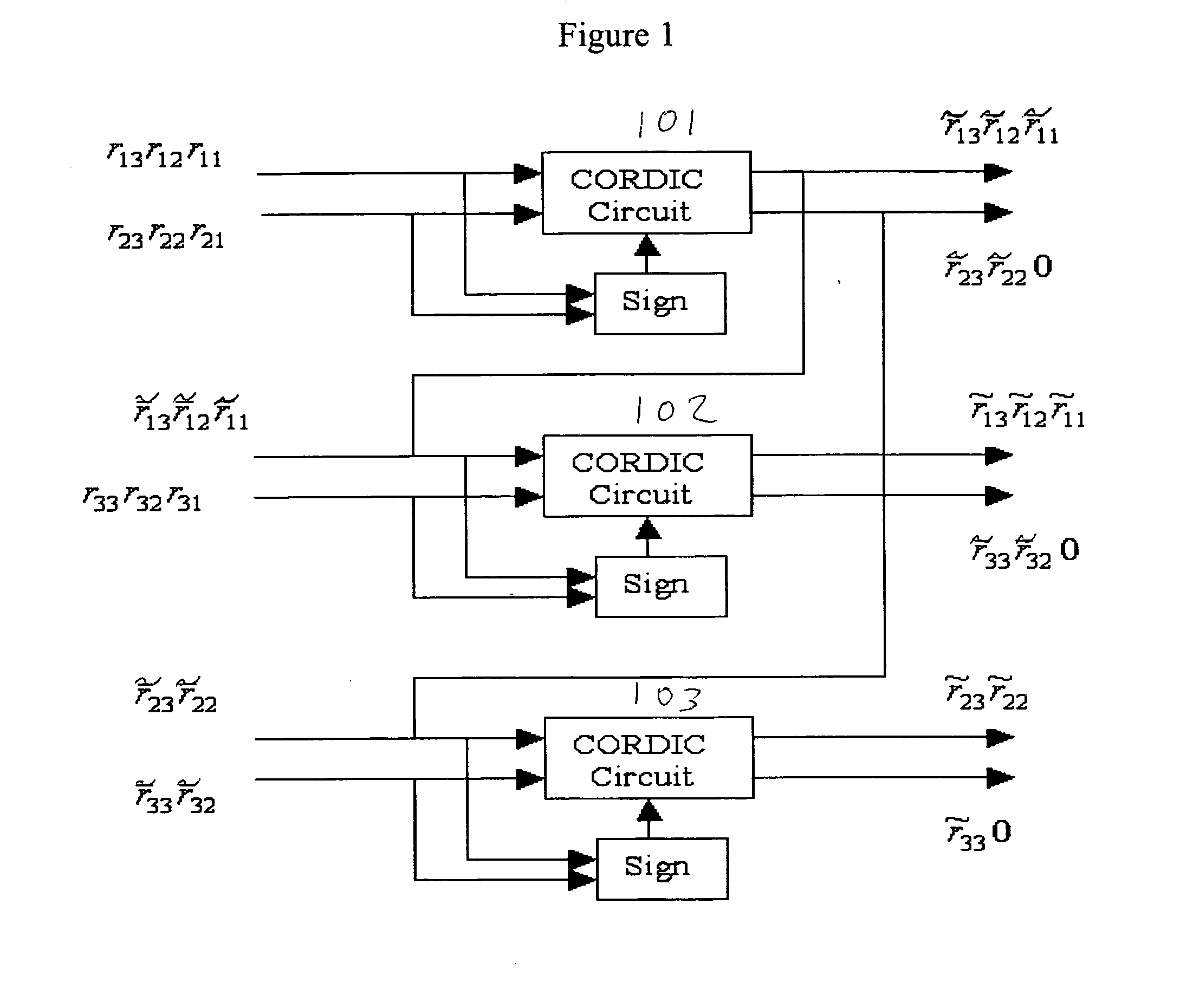
To implement Eq. (11), five modules are required: Module 1: Array of CORDIC circuits (101, 102, 103) shown in FIG. 1 where the pixel stream is fed into the module and the upper triangular matrix Rtupper is updated in real-time. Module 2: Apply backsubstitution to obtain the inverse of Rtupper invR. Module 3: Apply distributed arithmetic to calculate c=[(Rtupper)T]−1d=invRT*d. Module 4: Compute w=invRT*c. Module 5: The filter output energy can be obtained by applying a FIR filter to the current input pixel streams.
The detailed implementation for each of five modules is described as follows.
In Module 1, a set of CORDIC circuits (101, 102, 103) are applied to perform Givens rotation, as shown in FIG. 1. Values of r ...
second embodiment
In the invention for CEM implementation, the correlation matrix is calculated before QR-decomposition shown in FIG. 6. Since dTRL×L−1 in Eq. (5) is a constant, RL×L−1d represents relative strength of detection power. Letting w=RL×L−1d, i.e. RL×Lw=d, where RL×L−1d can be implemented by a CORDIC module and followed by a backsubstitution module. As a result, four modules are required to implement this modified CEM detector: Module 1: Auto-correlator. Module 2: Apply CORDIC circuits to triangularize [R|d]. Module 3: Apply backsubstitution to obtain w. Module 4: The filter output energy δCEM(r)=wTr can be obtained by applying a FIR filter to the current input pixel streams.
In Module 1, an auto-correlator generates the correlation matrix RL×L(i) with RL×L(i)=RL×L(i−1)+ririT and a pixel-by-pixel update process. In other words, the correlation matrix is updated every time a new pixel arrives. For illustrative purpose, let us assume L=3, then the new correlation matrix can be obtained ...
PUM
 Abstract
Description
Claims
Application Information
 - R&D
- Intellectual Property
- Life Sciences
- Materials
- Tech Scout
- Unparalleled Data Quality
- Higher Quality Content
- 60% Fewer Hallucinations
Browse by: Latest US Patents, China's latest patents, Technical Efficacy Thesaurus, Application Domain, Technology Topic, Popular Technical Reports.
© 2025 PatSnap. All rights reserved.Legal|Privacy policy|Modern Slavery Act Transparency Statement|Sitemap|About US| Contact US: help@patsnap.com


