Repair of combustion turbine components

a technology for combustion turbines and components, applied in the direction of machines/engines, manufacturing tools, machine/engines, etc., can solve the problems of cracks and spallations of superalloys and/or protective ceramic coatings, further complicating matters, and affecting the performance of components

Inactive Publication Date: 2005-01-27
SIEMENS ENERGY INC
View PDF10 Cites 83 Cited by
  • Summary
  • Abstract
  • Description
  • Claims
  • Application Information

AI Technical Summary

Benefits of technology

[0008] A method of repairing a combustion turbine component exposed to a high temperature operational environment using a welding technique adapted to repair cr

Problems solved by technology

Notwithstanding these protective efforts, the combustion turbine components nonetheless tend to suffer operational damage such as thermal fatigue, oxidation, corrosion, creep and the like, which typically causes cracking and spallation of the superalloy and/or protective ceramic coating.
To further complicate matters, these cracks and spallation are caused by a varie

Method used


Image

  • Repair of combustion turbine components
  • Repair of combustion turbine components

Examples


Embodiment Construction

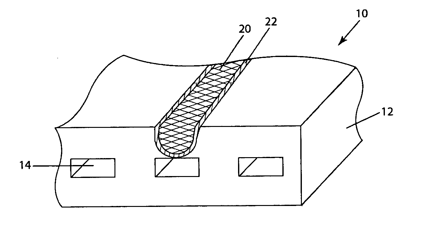
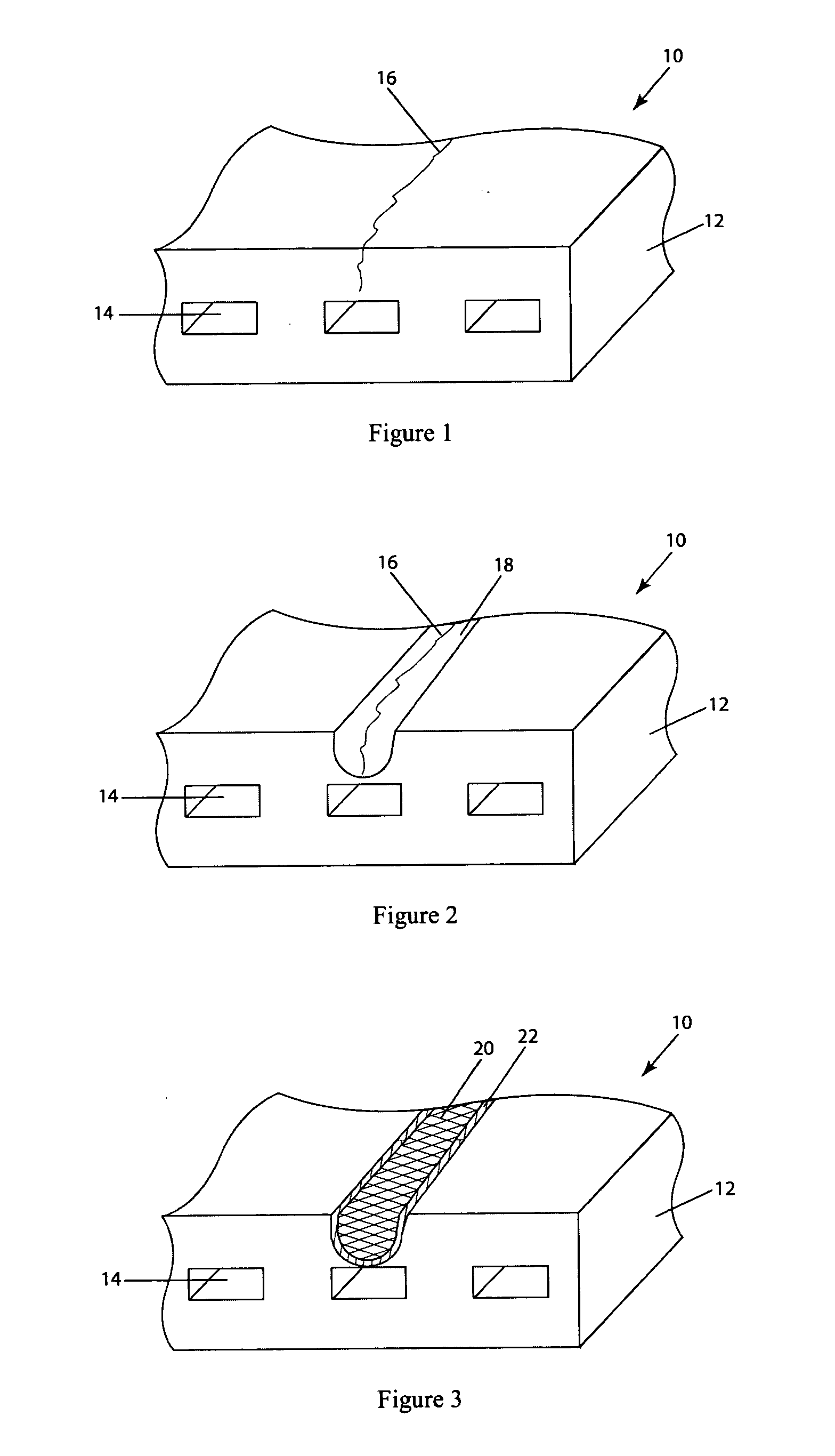
[0016] The invention described herein employs several basic concepts. For example, one concept relates to a method of repairing a cracked combustion turbine engine component where the crack is located near a hollow or geometrically complex portion of the component. Another concept relates to combustion turbine engine component repaired by a micro-plasma welding technique.

[0017] The present invention is disclosed in context of use as a transition duct 10 within a combustion turbine engine. The principles of the present invention, however, are not limited to transition ducts 10. For example, the principles of the present invention can be used to fabricate other combustion turbine components, such as combustion liners, combustion baskets, combustion nozzles, blades, vanes, and ring segments. For another example, the principles of the present invention can be used with aerospace applications, such as airplanes with combustion turbine engines. For another example, the principles of the ...


PUM

PropertyMeasurementUnit
Lengthaaaaaaaaaa
Fractionaaaaaaaaaa
Fractionaaaaaaaaaa

Abstract

A method of repairing a combustion turbine component having damage located at or near a cooling hole or hollow or geometrically complex portion of the component is provided. The method comprises forming a preparatory groove that extends from a surface of the component to the damaged area but does not extend to the cooling hole or hollow or geometrically complex portion of the component, the groove extending 40-90% the distance from the component to the damaged area; spraying a filler material into the groove with a micro-plasma torch at a current of less than 50 amperes; and filling the groove with the filler material such that the heated filler material substantially extends from the cooling hole or hollow or geometrically complex portion of the component to a surface of the component.

Description

CROSS REFERENCE TO RELATED APPLICATIONS [0001] This application claims the benefit of U.S. Provisional Application No. 60 / 468,396, filed May 6, 2003.FIELD OF THE INVENTION [0002] This invention relates generally to the field of combustion turbine component repair and in particular, to a repair technique adapted to weld cracks or other defects located near hollow or geometrically complex portions of the combustion turbine component. BACKGROUND OF THE INVENTION [0003] Gas turbine engines are known to include a compressor section for supplying a flow of compressed combustion air, a combustor section for burning fuel in the compressed combustion air, and a turbine section for extracting thermal energy from the combustion air and converting that energy into mechanical energy in the form of a rotating shaft. Many components that form the combustor and turbine sections are directly exposed to hot combustion gasses, for example, the combustor basket and liner and nozzles, the transition duc...

Claims


Application Information

Patent Timeline
IPC IPC(8): B23K10/02B23K35/02B23K35/32B23P6/00F01D5/00F01D5/18F01D9/02
CPCB23K10/027Y10T29/49742B23K35/0244B23K35/32B23K2201/001B23P6/007B23P2700/06F01D5/005F01D5/187F01D9/023Y02T50/67Y02T50/676Y10T29/49318Y10T29/49737Y10T29/49734Y10T29/49233B23K35/0227B23K2101/001Y02T50/60
Inventor KOTTILINGAM, SRIKANTH C.DITZEL, PETER J.
Owner SIEMENS ENERGY INC
Why Eureka
Try Eureka