
Metering roller for fuser release oil applicator

a technology of fuser release oil and metering roller, which is applied in the direction of manufacturing tools, portable power-driven tools, instruments, etc., can solve the problems of image quality defects in output prints, too much release oil on the fuser roller, and several types of image quality defects, so as to avoid image quality defects

Inactive Publication Date: 2005-01-27
EASTMAN KODAK CO
View PDF7 Cites 19 Cited by
  • Summary
  • Abstract
  • Description
  • Claims
  • Application Information

AI Technical Summary

Benefits of technology

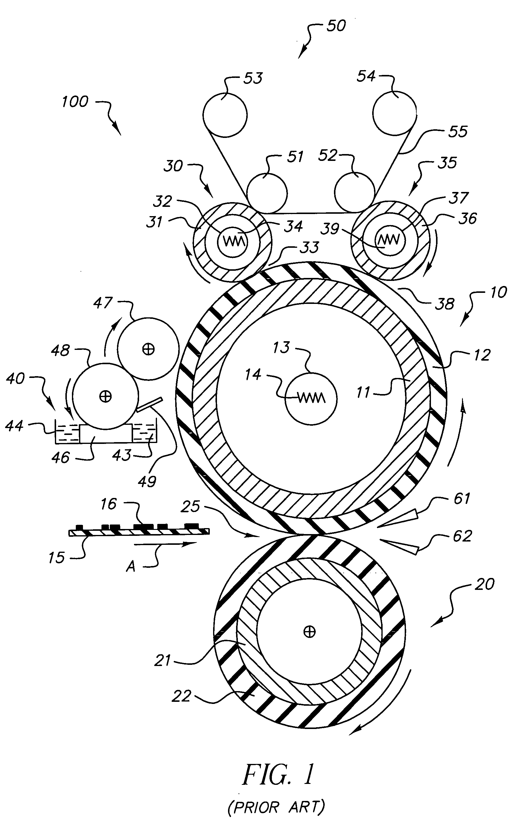
[0010] In view of the above, this invention is directed to an improved metering roller for a fuser release oil applicator. The release oil metering roller of this invention enables precise and consistent application of a predetermined target amount of release oil to the fuser roller of an electrostatographic reproduction apparatus fuser, thus avoiding image quality defects that result when the amount of release oil being applied to the fuser roller deviates from the predetermined target amount. Applicant has discovered a novel method of providing a surface finish on the release oil metering roller of this invention, the parameters of which can be varied to achieve a predetermined target release oil metering rate from within a range of rates, and which, additionally, precisely maintains the target metering rate under varying operating conditions.

Problems solved by technology

If the amount of release oil applied to the fuser roller deviates too much from the predetermined target amount or if it becomes too non-uniform, image quality defects will occur in the output prints.
A primary problem associated with too much release oil on the fuser roller occurs during duplex printing runs.
During these times some of the fuser release oil accumulated on the biased roller during duplex printing transfers to the photoconductive member.
Release oil on the photoconductive member causes several types of image quality defects including background and streaks due to non-uniform transfer from the photoconductive member to the receiver member.
These release oil related problems during duplex printing occur much sooner if oil in excess of the predetermined target amount is being applied to the fuser roller.
This problem will occur during simplex and duplex printing.

Method used


Image

  • Metering roller for fuser release oil applicator
  • Metering roller for fuser release oil applicator
  • Metering roller for fuser release oil applicator

Examples


example

[0034] An exemplary metering roller according to the method of this invention was prepared as follows:

[0035] 1. 316 L Stainless Steel tubing stock was ground to an outside diameter of 30.1 mm.

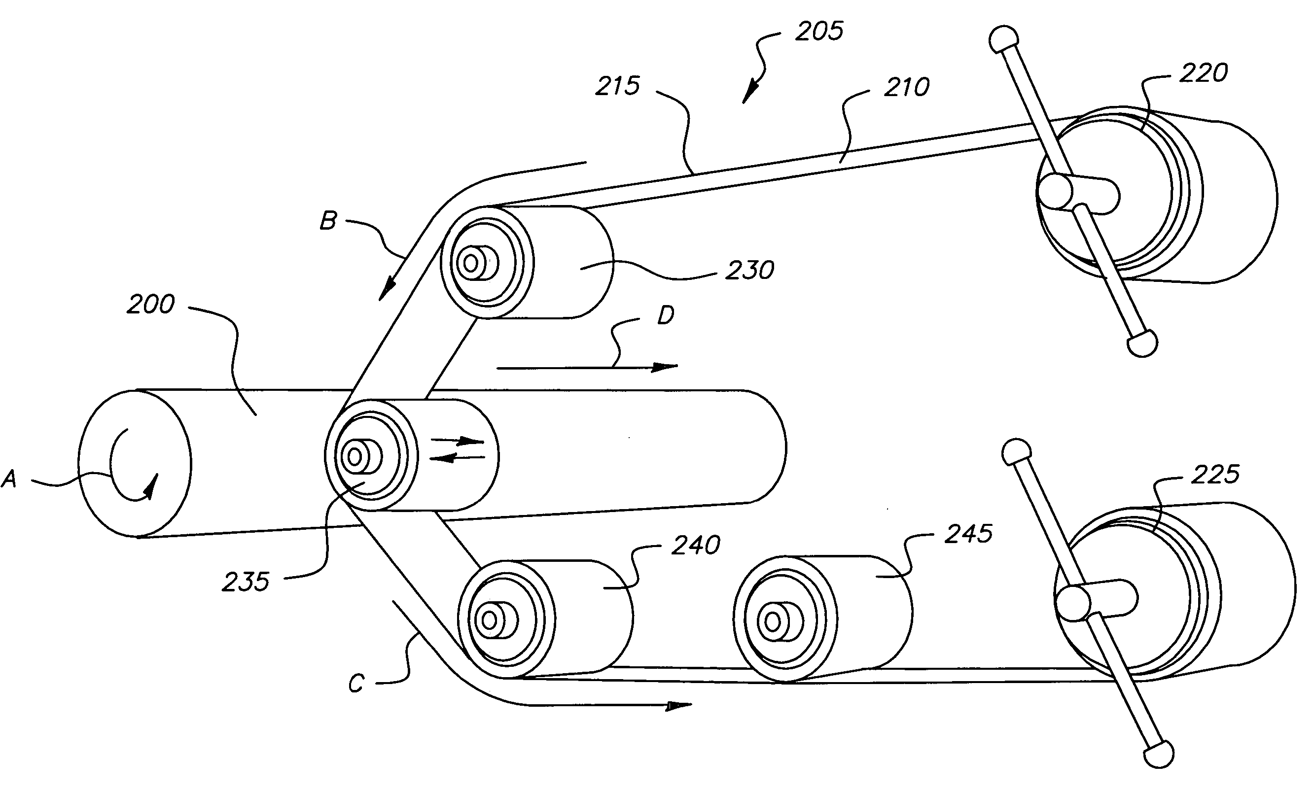
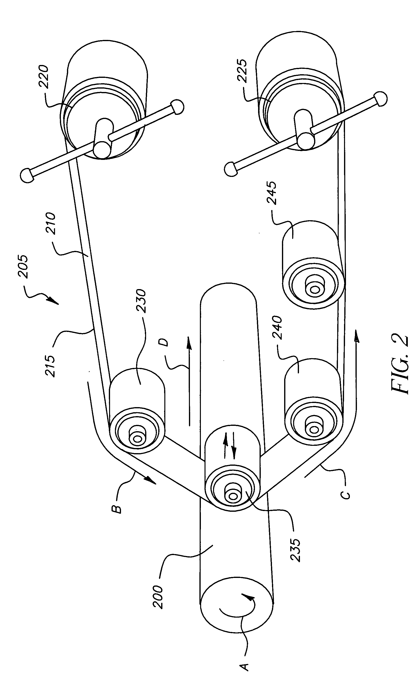
[0036] 2. The ground tubing stock was pre-finish polished by the method described above and depicted in FIG. 2 with the following set of parameters: [0037] Tubing stock rotational speed—570 rpm, [0038] Aluminum Oxide abrasive grit—30 microns, [0039] Flexible belt feed rate—4.0 inches / minute, [0040] Pressure applies to tubing stock by roller 235—13 psi, [0041] Steady axial speed of polishing apparatus—35 inches / minute, [0042] Axial oscillating speed of polishing—8.3 cycles / second.

[0043] 3. The pre-finished tubing stock was electroplated with Nickel to a thickness of 8 microns.

[0044] 4. The plated tubing stock was heat treated by steadily increasing the temperature of the stock from ambient temperature to 750° F. in one hour, maintaining the temperature at 750° F. for three hours, and steadil...


PUM

PropertyMeasurementUnit
Temperatureaaaaaaaaaa
Lengthaaaaaaaaaa
Timeaaaaaaaaaa

Abstract

A metering roller, for a fuser release oil applicator, which enables precise and consistent application of a predetermined target amount of release oil to the fuser roller. Starting with tubing stock that has been machined and course ground to a final outside diameter, the metering roller is produced by initial pre-finish polishing, electroplating with Nickel, heat treatment to achieve a hardened surface, and final post-finish polishing. Both pre-finish and post-finish polishing steps are performed on a lathe with continuously fed polishing paper according to a parameter recipe that includes lathe spindle rpm and lead screw speed, and polishing paper grit, feed rate, pressure, and oscillatory rate.

Description

FIELD OF THE INVENTION [0001] This invention relates generally to electrostatographic reproduction apparatus, and more particularly, to metering rollers in fuser release oil applicators. BACKGROUND OF THE INVENTION [0002] In typical electrostatographic reproduction apparatus, a latent image charge pattern is formed on a uniformly charged charge-retentive member or photoconductor having dielectric characteristics. Charged thermoplastic, pigmented marking particles are attracted to the latent image charge pattern to render the latent image visible. A receiver member, such as a sheet of paper, transparency, or other medium, is then brought into contact with the photoconductive member, and an electric field applied to transfer the marking particle developed image to the receiver member from the photoconductive member. The electric field to transfer the marking particle developed image to the receiver member from the photoconductive member is typically applied by spraying the backside of...

Claims


Application Information

Patent Timeline
IPC IPC(8): B21K1/02G03G15/20
CPCG03G2215/2093Y10T29/49563G03G15/2025
Inventor BERG, RICHARD H.
Owner EASTMAN KODAK CO
Learn More