Method of testing seismic braces

a technology of seismic braces and braces, applied in the field of method of testing braces, can solve the problems of significant degradation of brace components in strength, stiffness, energy dissipation, etc., and achieve the effect of simple, yet rational protocol, degradation of strength, stiffness, and energy dissipation

Active Publication Date: 2005-01-27
FACTORY MUTUAL RES
View PDF34 Cites 3 Cited by
  • Summary
  • Abstract
  • Description
  • Claims
  • Application Information

AI Technical Summary

Benefits of technology

Tests have shown that the brace components can exhibit significant degradation in strength, stiffness, and energy dissipation under cyclic conditions.

Problems solved by technology

Tests have shown that the brace components can exhibit significant degradation in strength, stiffness, and energy dissipation under cyclic conditions.

Method used


Image

  • Method of testing seismic braces
  • Method of testing seismic braces
  • Method of testing seismic braces

Examples


Embodiment Construction

The following description is written in terms of sprinkler pipes in a building, but the present invention also encompasses objects other than sprinkler pipes and fixed structures other than buildings.

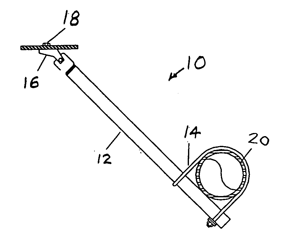
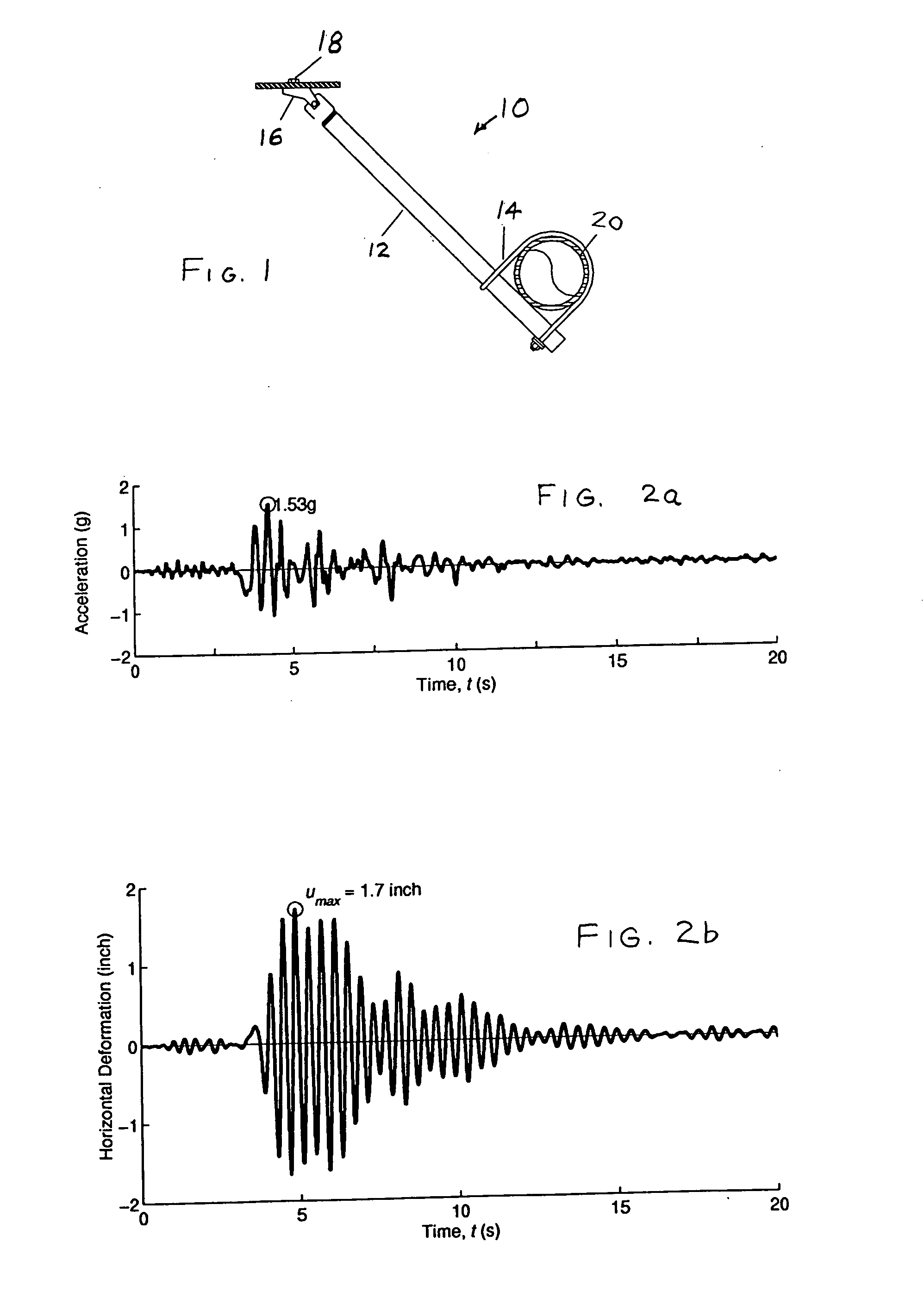
The components of a “rigid” seismic brace 10 are shown in FIG. 1. These are a brace pipe 12, a pipe-attached component 14, a building-attached component 16, including a fastener 18. The pipe-attached component 14 is attached to a sprinkler pipe 20. The pipe-attached component 14, the building-attached component 16, or both can comprise a single member, a plurality of inseparable members, or a subassembly of separable members. The deformation history for the brace 10 can be obtained by dividing the force history by the stiffness of the brace assembly. Under strong shaking, the seismic loads are so large that the brace 10 is likely to yield. Its stiffness, therefore, depends on the applied load.

FIG. 2a shows the acceleration history at the roof of a 6-story hospital building shaken by...


PUM


Abstract

Braces for bracing objects in structures against forces due to earthquakes are tested by subjecting components of the braces for attaching the braces to the object or structure to cyclic loading of approximately 15 cycles. The cyclic forces are applied to different samples of the components at differing angles, and a load rating is determined for each angle. Prior to cyclic testing, forces are applied monotonically to the components in both tension and compression, the flexible loading direction of the component is determined from the monotonic testing, and the deformation that the component can resist when a load is applied in cycles is estimated from the monotonic testing.

Description

BACKGROUND OF THE INVENTION The present invention relates to a method of testing braces designed to restrain objects relative to a fixed structure during an earthquake, for example, to restrain sprinkler pipes in a building. Design codes and standards (e.g., Uniform Building Code, International Building Code, NFPA-13 (National Fire Protection Association)) estimate the amplitude of the seismic load in sprinkler-pipe braces, but they do not specify the number of cycles for which this load must be resisted by various components of pipe braces. The sprinkler pipes in a building are typically supported from the roof or the floor above by hanger rods that are designed to transfer the gravity load from the pipes to the supporting structure. In seismic regions, the pipes need to be restrained laterally and longitudinally at discrete locations along their length by seismic braces. In an earthquake, inadequately restrained sprinkler piping can suffer damage by large differential movement ...

Claims


Application Information

Patent Timeline
Patent Type & Authority Applications(United States)
IPC IPC(8): E04H9/02
CPCE04H9/028E04H9/02E04H9/0237F16L3/10
Inventor MALHOTRA, PRAVEEN K.SENSENY, PAUL E.BRAGA, ANTONIO CARLOS M.ALLARD, ROGER L.
Owner FACTORY MUTUAL RES
Why Eureka
Try Eureka