Stirling cooling device, cooling chamber, and refrigerator

a cooling device and cooling chamber technology, applied in the direction of cooling fluid circulation, domestic cooling apparatus, lighting and heating apparatus, etc., can solve the problems of poor heat transmission efficiency, high volatile, and use of ethanol, and achieve the effect of efficient transfer, efficient release, and improved heat transmission efficiency

Inactive Publication Date: 2005-01-27
SHARP KK
View PDF10 Cites 8 Cited by
  • Summary
  • Abstract
  • Description
  • Claims
  • Application Information

AI Technical Summary

Benefits of technology

[0022] In these refrigerators configured as described above, the use of latent heat obtained through vaporization and liquefaction of the refrigerant contributes to better heat transmission efficiency than when sensible heat is exploited. Thus, cold is efficiently transferred to inside the refrigerator chamber, or heat is efficiently released to outside the refrigerator chamber. This helps enhance the heat exchange efficiency of refrigerators.
[0023] Moreover, the condenser and the evaporator can be formed in the desired sizes. This makes it possible to efficiently transfer the heat in the low-temperature and high-temperature portions, of which the sizes are limited in consideration of the efficiency of the reverse Stirling cycle, to air, which has low thermal conductivity. This helps realize large-capacity refrigerators.
[0024] Moreover, the refrigerant is circulated by exploiting the difference in height, without the use of external power prepared specially for the circulation of the refrigerant. This helps realize low-power-consumption refrigerators.
[0025] In the refrigerators according to the present invention, a gas-liquid separator may be provided additionally. This helps increase the flow rate of the refrigerant circulated.
[0026] In the refrigerators according to the present invention, as the refrigerant, carbon dioxide or water may be used, which is a non-flammable, non-toxic natural refrigerant. This helps realize refrigerators friendly to humans and to the global environment.
[0027] In the refrigerators according to the present invention, the height of the refrigerators may be used effectively to arrange the low-temperature-side and high-temperature-side heat exchanger portions. Moreover, the refrigerator chamber may be divided into an upper section serving as a refrigerator compartment, a middle section serving as a vegetables compartment, and a lower section serving as a freezer compartment. This contributes to effective use of the cold air inside the refrigerator chamber.

Problems solved by technology

In this arrangement, however, since the cold is transferred by exploiting the sensible heat of the secondary refrigerant, temperature difference arises within the refrigerant pipe 25, leading to poor heat transmission efficiency.
Moreover, ethanol used as the secondary refrigerant has a low flash point (about 12.8° C.) and is highly volatile, requiring care in its handling.
This increases the load on the refrigerant pump 26, and thus reduces the energy efficiency of the Stirling cooling apparatus.

Method used


Image

  • Stirling cooling device, cooling chamber, and refrigerator
  • Stirling cooling device, cooling chamber, and refrigerator
  • Stirling cooling device, cooling chamber, and refrigerator

Examples


first embodiment

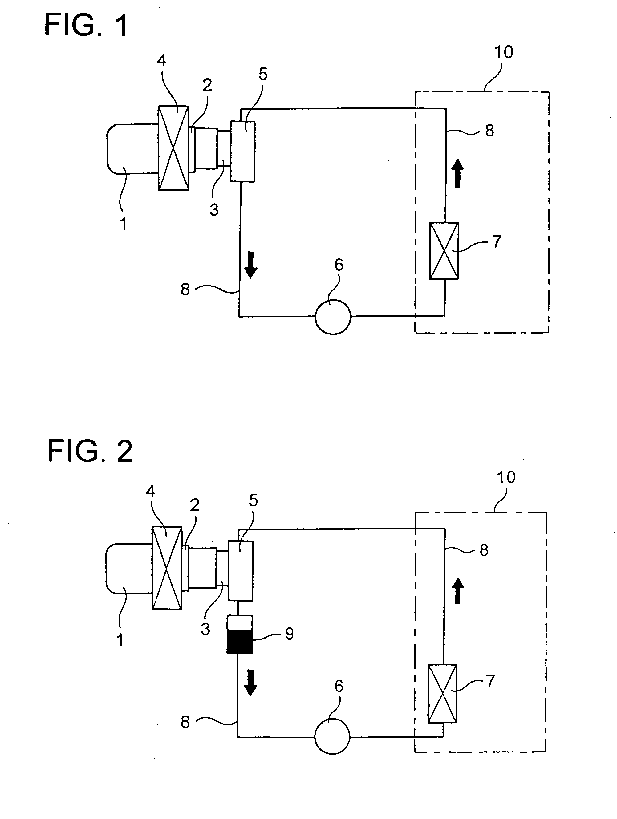
[0045] In the figure, arrows indicate the direction of the flow of the refrigerant. In this embodiment, carbon dioxide is used as the refrigerant. The configuration and operation of the Stirling chiller 1 shown in FIG. 2 are the same as in the first embodiment described above, and therefore its explanations will not be repeated.

[0046] When the linear motor (not shown) is driven, on the principle described earlier, waste heat is transferred to the high-temperature portion 2 of the Stirling chiller 1, raising the temperature of the high-temperature portion 2, and simultaneously cryogenic cold is produced in the low-temperature portion 3. Then, in the high-temperature-side heat exchanger 4 arranged so as to be in contact with the high-temperature portion 2, the waste heat is released out of the Stirling chiller 1 by air or water used as a heat carrier.

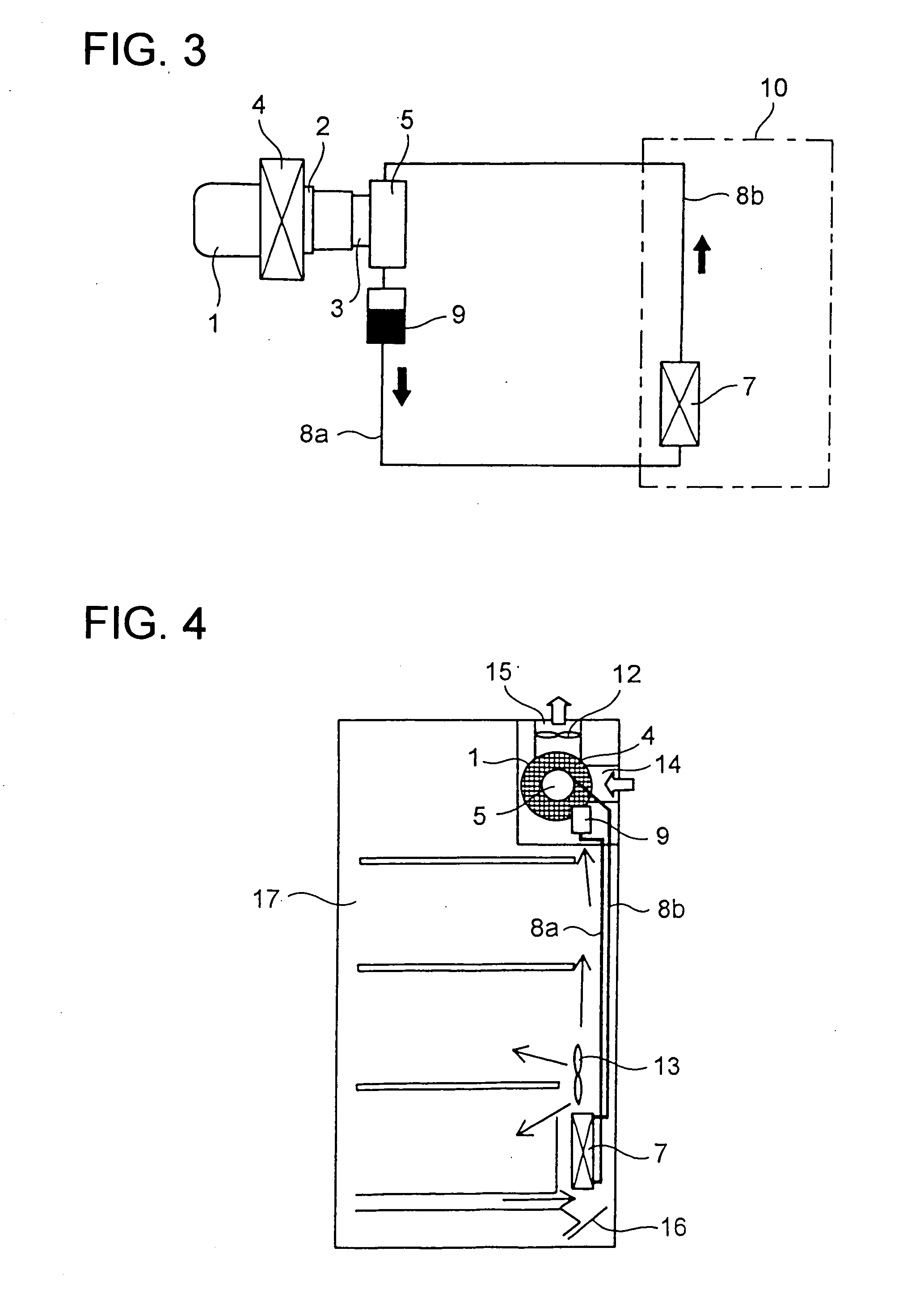
[0047] Simultaneously, the circulation pump 6 is also driven so that the refrigerant is circulated around the refrigerant circulation c...

fifth embodiment

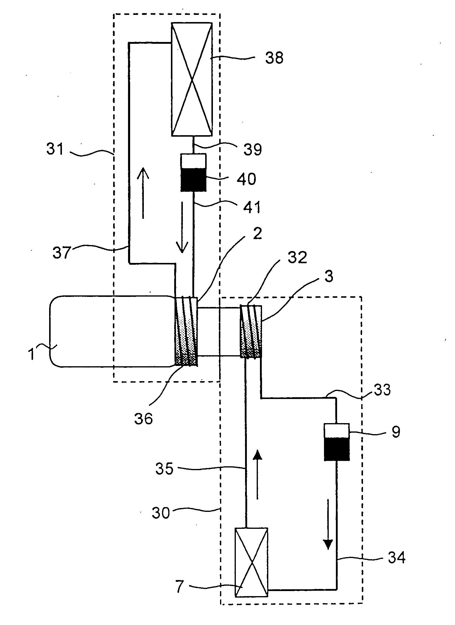
[0083] In this way, by incorporating the chiller system of the fifth embodiment in a large, horizontal-type refrigerator, it is possible to effectively exploit the height of the refrigerator in the arrangement of the low-temperature-side heat exchanger portion 30 and the high-temperature-side heat exchanger portion 31. Moreover, by arranging the freezer compartment 46 nearest to the low-temperature-side evaporator 7 and arranging the vegetables compartment 45 under the refrigerator compartment 44, it is possible to effectively use the cold air inside the refrigerator chamber of the refrigerator 42.

[0084] Industrial Applicability

[0085] As described above, according to the present invention, the use of latent heat obtained through vaporization and liquefaction of the refrigerant contributes to better heat transmission efficiency than when sensible heat is exploited. Thus, cold is efficiently transferred to inside the refrigerator or cooler chamber, or heat is efficiently released to ...


PUM


Abstract

In a Stirling cooling apparatus, a refrigerant is circulated within a refrigerant circulation circuit in such a way that the refrigerant receives cold, as latent heat, from a Stirling chiller and then releases the cold, by absorbing heat of vaporization, as it vaporizes in an evaporator, thereby cooling the inside of a refrigerator chamber. As the refrigerant, carbon dioxide, a natural refrigerant, can be suitably used.

Description

TECHNICAL FIELD [0001] The present invention relates to a cooling apparatus, cooler, and refrigerator employing a Stirling chiller. BACKGROUND ART [0002] As is well known, conventionally, refrigerants based on CFCs (chlorofluorocarbons) and HCFCs (hydrochlorofluorocarbons) have been in wide use as working fluids in chilling and air-conditioning systems. However, refrigerants based on CFCs have already been totally banned, and the use of refrigerants based on HCFCs is regulated by the international treaty for the protection of the ozone layer. On the other hand, newly developed refrigerants based on HFCs (hydrofluorocarbons) do not destroy the ozone layer, but are powerful global warming substances having global warming coefficients as high as several hundred to several thousand times that of carbon dioxide. Thus, these are also targets of emission regulation. [0003] For this reason, as an alternative technology to the vapor-compression cooling cycle which uses a refrigerant mentione...

Claims


Application Information

Patent Timeline
Patent Type & Authority Applications(United States)
IPC IPC(8): F25D17/00F25B1/00F25B9/14F25B25/00F25D11/00F25D11/02F25D16/00F25D17/06
CPCF25B9/14F25B25/005F25D17/062F25D11/00F25D11/025F25B2309/06
Inventor ZHANG, HENGLIANGCHEN, WEINISHIMOTO, TAKASHIMASUDA, MASAAKI
Owner SHARP KK
Why Eureka
Try Eureka