Photoresist coating system

a coating system and photoresist technology, applied in the field of photoresist coating systems, can solve the problems and achieve the effects of shortening the time required for switching photoresist, shortening the storage time of photoresist solutions, and reducing the amount of photoresist solutions used

Inactive Publication Date: 2005-01-27
AU OPTRONICS CORP
View PDF6 Cites 16 Cited by
  • Summary
  • Abstract
  • Description
  • Claims
  • Application Information

AI Technical Summary

Benefits of technology

[0009] It is therefore a primary objective of the claimed invention to provide a photoresist coating system having a cooling system and a heating system to control a temperature of photoresist solution so that a photoresist spin coating process can be performed successfully.
[0011] Since the present invention photoresist coating system comprises a cooling system and a heating system, the photoresist solutions not used yet can be kept at a low temperature to prolong the storage time of the photoresist solutions. Moreover, the temperature of the photoresist solutions transferred from the photoresist bottles can be increased to room temperature to allow the photoresist solutions to be switched at any time. As a result, the present invention photoresist coating system not only shortens the time required for switching photoresist solutions when the process is changed, but also obviously decreases the amount of the photoresist solutions used. The processing cost is thus reduced.

Problems solved by technology

As a result, the present invention photoresist coating system not only shortens the time required for switching photoresist solutions when the process is changed, but also obviously decreases the amount of the photoresist solutions used.

Method used


Image

  • Photoresist coating system
  • Photoresist coating system
  • Photoresist coating system

Examples


Embodiment Construction

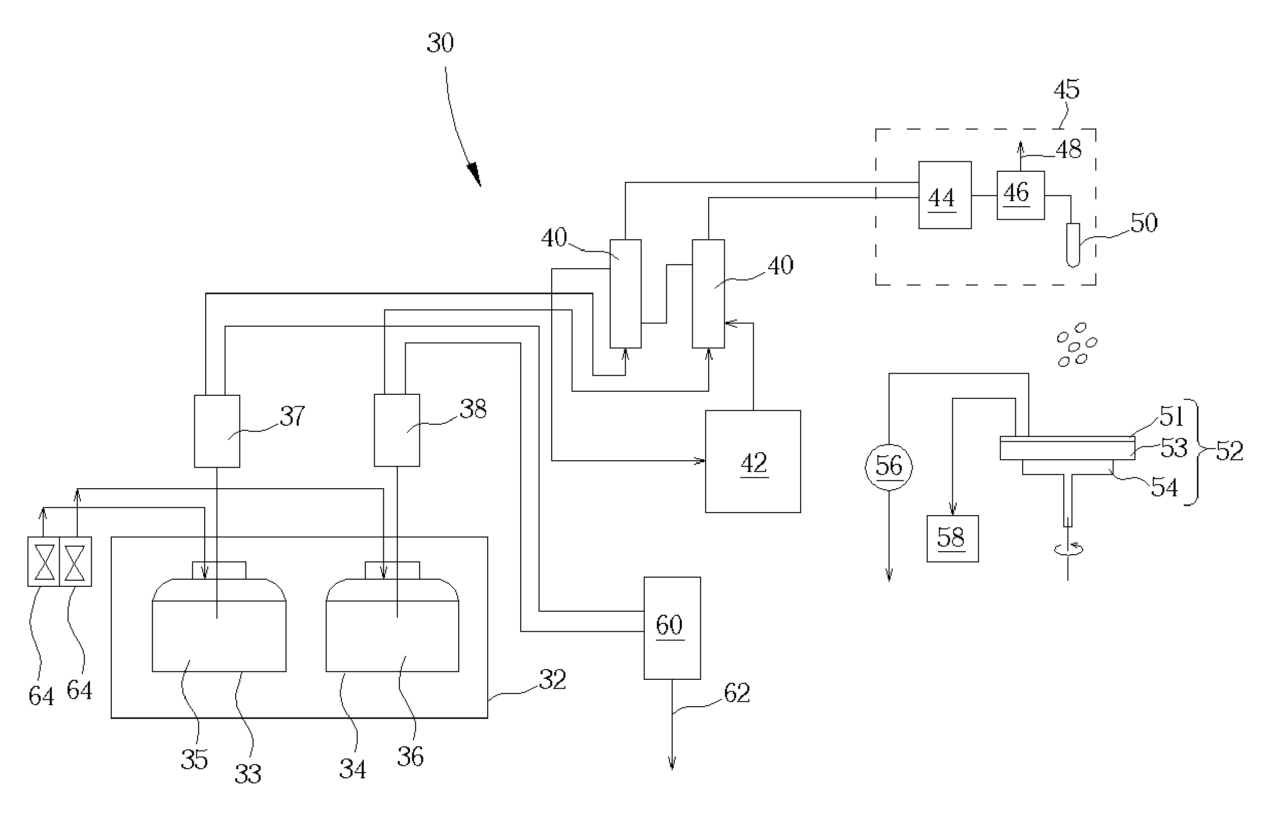
[0016] Please refer to FIG. 3. FIG. 3 is a structural schematic diagram of a present invention photoresist coating system 30. As shown in FIG. 3, the present invention photoresist coating system 30 mainly comprises a chemical tank 32 for positioning a plurality of photoresist bottles, depending on the requirements of processes. In a preferred embodiment of the present invention, two photoresist bottles 33, 34 are taken as an example for illustration. The photoresist bottles 33, 34 are respectively used for storing photoresist solutions 35, 36 supplied to the photoresist coating system 30. The photoresist coating system 30 further comprises a cooling system 40 for chilling the photoresist solutions 35, 36 in the photoresist bottles 33, 34, a heating system 42 for heating the photoresist solutions 35, 36 transferred from the photoresist bottles 33, 34, an automatic photoresist feed system 45 for draining and delivering the photoresist solutions 35, 36, and a gyrate system 52 for posit...


PUM

PropertyMeasurementUnit
temperatureaaaaaaaaaa

Abstract

The present invention discloses a photoresist coating system. The photoresist coating system mainly includes a chemical tank for positioning at least one photoresist bottle that is used for storing photoresist solution supplied to the photoresist coating system, a cooling system for chilling the photoresist solution in the photoresist bottle to a low temperature, a heating system for heating the photoresist solution transferred from the photoresist bottle to an adequate temperature, and an automatic photoresist feed system for draining and delivering the photoresist solution.

Description

BACKGROUND OF INVENTION [0001] 1. Field of the Invention [0002] The present invention relates to a photoresist coating system applied in photolithography processes, and more particularly, to a photoresist coating system having a cooling system and a heating system to preserve photoresist solution not used yet at a low temperature to avoid undergoing a chemical change and to heat transferred photoresist solution to a room temperature at any time to supply a production line. [0003] 2. Description of the Prior Art [0004] A photolithography process is utilized very extensively. When fabricating devices, such as semiconductor devices, opto-electronics devices, etc., the photolithography process is utilized to transfer electronic components and circuits, in a layer upon layer manner, to a substrate including a wafer or a plastic substrate. Generally speaking, a photolithography process includes three fundamental steps: photoresist coating, exposure, and development. The photoresist soluti...

Claims


Application Information

Patent Timeline
Patent Type & Authority Applications(United States)
IPC IPC(8): B05C11/08B05C11/10G03F7/16
CPCB05C11/08G03F7/162G03F7/16B05C11/1042
Inventor CHEN, WANG-SHENGTSENG, TSENG-KUEI
Owner AU OPTRONICS CORP
Why Eureka
Try Eureka