Arrangement for optimizing the pulse shape in a laser scanning microscope

a laser scanning microscope and shape technology, applied in the direction of lasers, instruments, electric discharge lamps, etc., can solve the problems of inability to determine the optimal conditions for excitation of nonlinear contrasts, and the inability to create the optimal conditions by conventional techniques

Inactive Publication Date: 2005-01-27
CARL ZEISS MICROSCOPY GMBH
View PDF3 Cites 27 Cited by
  • Summary
  • Abstract
  • Description
  • Claims
  • Application Information

AI Technical Summary

Benefits of technology

In accordance with the invention, a device for coupling a short laser into a microscope beam comprises a dispersive element for spatially separating the spectral components of the laser radiation, means for manipulating individual spectral components and another dispersive element for spatially superimposing the manipulated individual spectral components.

Problems solved by technology

However, higher-order dispersions which cannot be determined beforehand must be taken into account, e.g., in biological preparations.
Therefore, it is not possible to create optimum conditions for the excitation of nonlinear contrasts by conventional techniques.
On the other hand, it is disadvantageous when the emission wavelength bands of the individual dyes overlap because the dyes can then no longer be spectrally separated.

Method used


Image

  • Arrangement for optimizing the pulse shape in a laser scanning microscope
  • Arrangement for optimizing the pulse shape in a laser scanning microscope
  • Arrangement for optimizing the pulse shape in a laser scanning microscope

Examples


Embodiment Construction

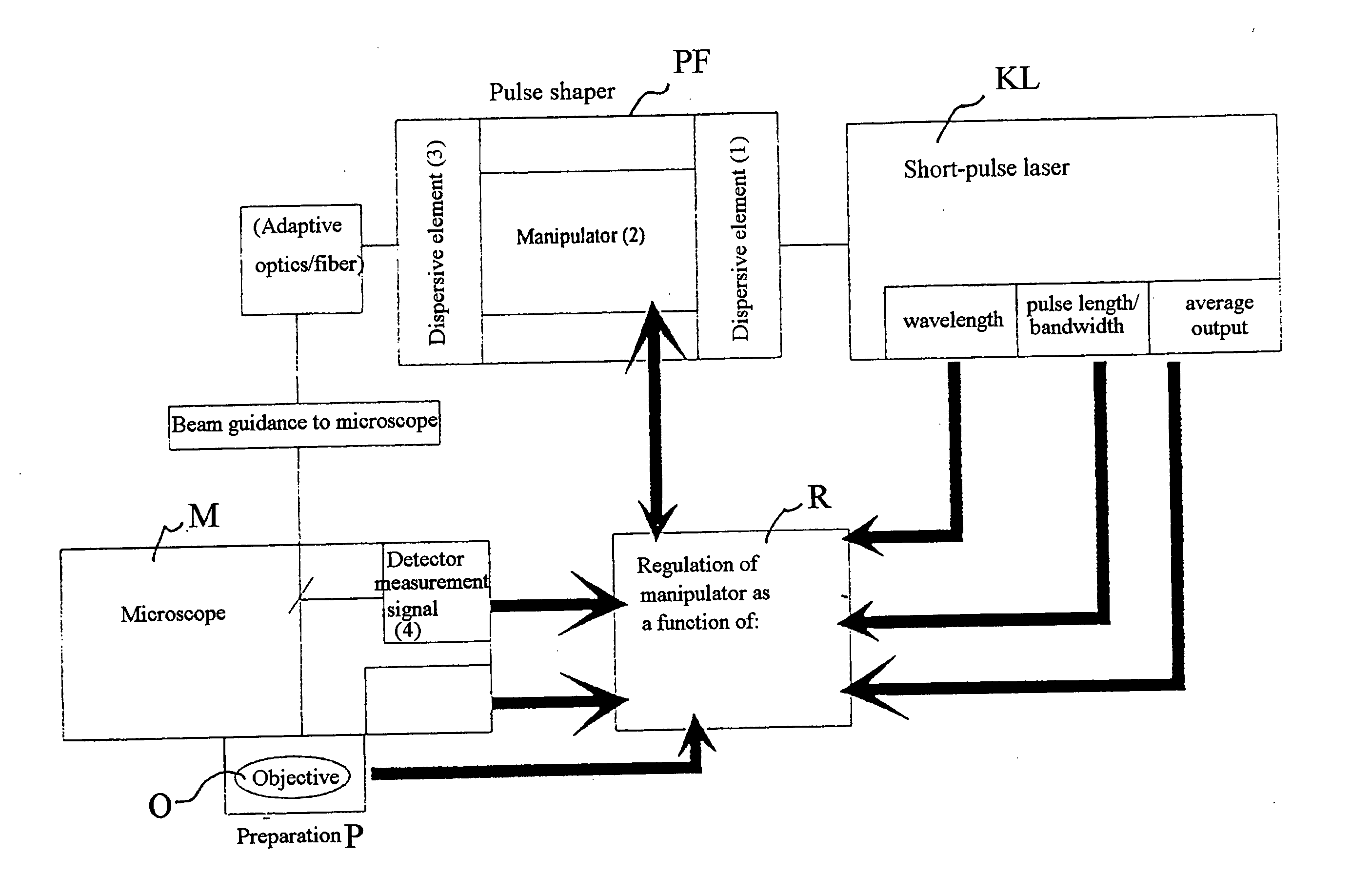
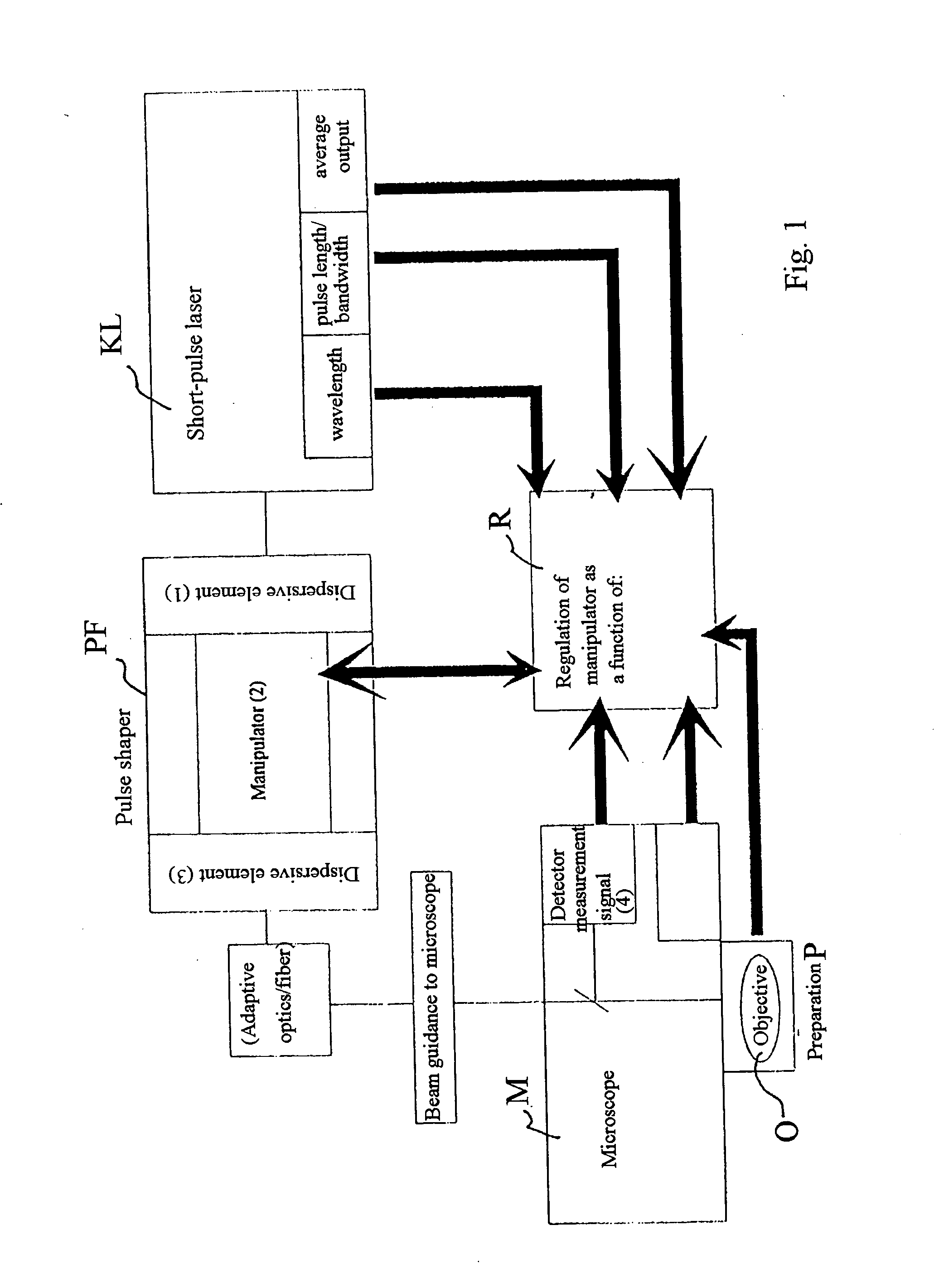
The light pulses proceed from the short pulse laser KL to the pulse shaper PF. The latter is shown schematically in FIG. 2a. In the pulse shaper PF, the incident beam (beam in) is spatially split into the spectral components of the light pulses in a first dispersive element (1) comprising, e.g., a grating or prisms. A Fourier plane is then generated by means of an achromatically corrected lens or lens group L1 (FIG. 2).

This plane (focal plane) is characterized in that the individual spectral components of the light pulses are spatially separated. Considered mathematically, the transformation into this plane corresponds to a Fourier transform. In this plane, a spatial light modulator (2) (SLM) is used in transmission. The modulator is also referred to herein as a manipulator of spectral components. Generally, it comprises a matrix of nematic liquid crystals (e.g., SLM-S160 / h, Jenoptik LOS) in helical or parallel arrangement. The transmission and phase displacement of the correspon...


PUM

PropertyMeasurementUnit
laser scanning microscopeaaaaaaaaaa
phase modulationaaaaaaaaaa
higher-order dispersionaaaaaaaaaa

Abstract

A Device for coupling a short pulse laser into a microscope beam path, wherein the spectral components of the laser radiation are spatially separated by means of a dispersive element, the individual spectral components are manipulated and are then spatially superimposed again by means of another dispersive element.

Description

BACKGROUND OF THE INVENTION a) Filed of Invention At present, nonlinear contrasts such as two-photon absorption or second harmonic generation (SHG) are used to an increasing extent in microscopy, e.g., for examination of biological preparations. It is advantageous to use short pulse lasers to provide the energy needed to excite nonlinear effects. In this connection, the peak pulse power should be as high as possible and the pulse length at the location of the specimen should accordingly be as small as possible to prevent damage to the preparation simultaneously. Short pulse lasers supply light pulses, for example, of several 10 fs at a repetition rate of several 10 MHz. Accordingly, they have the advantage that they emit extremely high peak pulse energies accompanied at the same time by low average output. It is disadvantageous that the short pulses on the path through the microscope to the specimen change due to the group velocity dispersion (GVD)—usually, they become longer. b...

Claims


Application Information

Patent Timeline
Patent Type & Authority Applications(United States)
IPC IPC(8): G02B21/00G01N21/64G02B21/06G02B21/16
CPCG02B21/002H01S3/0057G01J3/0229G02B27/4244G01J2003/1213G01J3/1804
Inventor WOLLESCHENSKY, RALFFEURER, THOMASSAUERBREY, ROLAND
Owner CARL ZEISS MICROSCOPY GMBH
Why Eureka
Try Eureka