Interposer

Inactive Publication Date: 2005-01-27
CLAYTON GARY +1
View PDF10 Cites 91 Cited by
  • Summary
  • Abstract
  • Description
  • Claims
  • Application Information

AI Technical Summary

Benefits of technology

[0018] One version of the device is made of an elastomeric material embedded with conductive metallic granules, in which the conductive metallic granules make up approximately seventy to ninety per

Problems solved by technology

A problem with devices involving a protruding electrode is that under higher frequencies, the protruding electrode can act as a radio antennae, and energy losses due to radio frequency transmission and subsequent diffusion of the energy are detrimental to the circuit.
There are several problems with this design The conductive particles are large enough that when the column is compressed and an electric current is passed through the column, there may be only one or a few conductive pathways through the particles.
Another problem is that the columns can only be as small as the electromagnets can make them, and they can only be as tightly packed as the electromagnets can be packed.
Currently, the pitch between the columns (the center to center spacing between the columns) and the diameter of the columns are not small enough to accommodate very small electrical components.
Furthermore, if the particles are made smaller, the electromagnets would have that much less influence on each particle, and could not pack the columns as tightly.
Therefore, there are some inherent limitations in this method of making conductive columns in an elastomeric material.
The problem with this kind of interposer is that if the number of particles is increased in order to provide better conductivity, then there is increased leakage of the current to the sides of the compressed area.
If there are not enough particles in this material, then the resistance is high because the route from edge to edge through the inter

Method used


Image

  • Interposer
  • Interposer
  • Interposer

Examples


Example

[0061] While the invention is susceptible of various modifications and alternative constructions, certain illustrated embodiments thereof have been shown in the drawings and will be described below in detail. It should be understood, however, that there is no intention to limit the invention to the specific forms or processes disclosed, but, on the contrary, the invention is to cover all modifications, alternative constructions, and equivalents falling within the spirit and scope of the invention as defined in the claims.

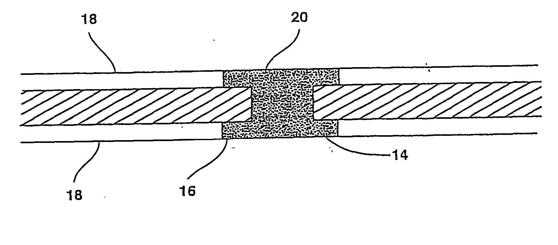
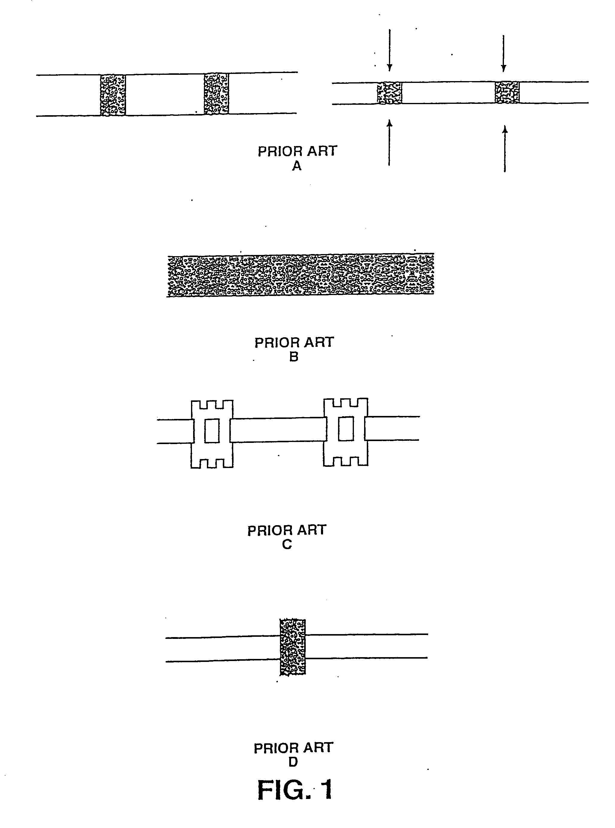
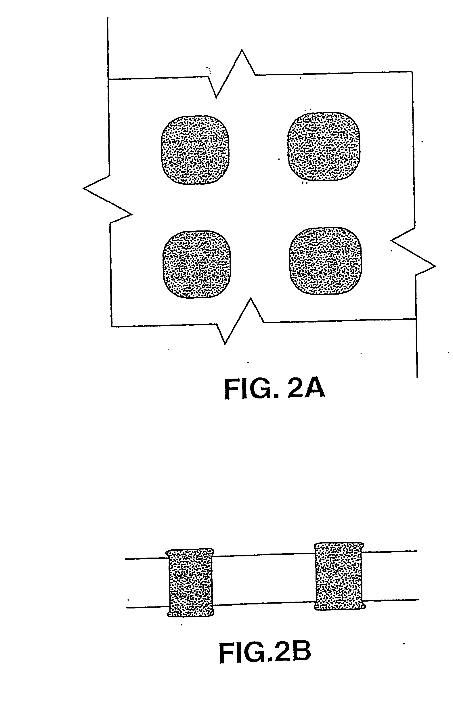
[0062] Several embodiments of the improved interposer are shown in the accompanying drawings. Also included in the drawings are descriptions of several methods of making the improved interposer. The problem with the prior art interposers as shown in FIGS. 1A though 1D, are solved by the interposer of the current design, which results in an interposer with elastomeric contacts, which are also sufficiently conductive that many conductive pathways are created from one...


PUM


Abstract

An improved interposer for use in forming an electrical connection between electrical components. The interposer includes a bi-lobate contact pad made of an elastomeric material embedded with conductive metallic granules.

Description

BACKGROUND OF THE INVENTION [0001] 1. Field of the Invention [0002] The present invention generally relates to semiconductor and package testing, as well as electrical interconnections, and more particularly relates to a thin, flexible device for making electrical connections between two electrical components, called an interposer. [0003] 2. Background Information [0004] There are a number of ways that one electrical component is attached to another electrical component. A chip being attached to a circuit board is one example. The goal of such a connection is to have good electrical conductivity, efficient assembly, and economical manufacture. This task has been accomplished in the past by probes being inserted into a socket, which may be soldered in place, or held by friction fit devices of various kinds. A problem with devices involving a protruding electrode is that under higher frequencies, the protruding electrode can act as a radio antennae, and energy losses due to radio freq...

Claims


Application Information

Patent Timeline
IPC IPC(8): H01L23/498H01R13/24H05K3/32H05K3/40
CPCH01L23/49827H01L23/49883H01R13/2414H05K3/325H05K3/4069H05K2201/0166H05K2201/0314H01L2924/0002H05K2201/10378H05K2203/0568H05K2203/0769H05K2203/1572H01L2924/00
Inventor CLAYTON, GARYHASTINGS, DOUGLAS G.
Owner CLAYTON GARY
Why Eureka
Try Eureka