Integrated circuit package testing device and method

a technology of integrated circuits and testing devices, which is applied in the direction of measurement devices, printed circuits, instruments, etc., can solve the problems of large disparity in contact pressure between the contacts of the socket and the contact sections of the packag

Inactive Publication Date: 2005-01-27
WELLS CTI LLC
View PDF4 Cites 3 Cited by
  • Summary
  • Abstract
  • Description
  • Claims
  • Application Information

AI Technical Summary

Problems solved by technology

Unless the tolerance of package thickness is accounted for in the design and manufacture of this type of socket, there

Method used


Image

  • Integrated circuit package testing device and method
  • Integrated circuit package testing device and method
  • Integrated circuit package testing device and method

Examples


Embodiment Construction

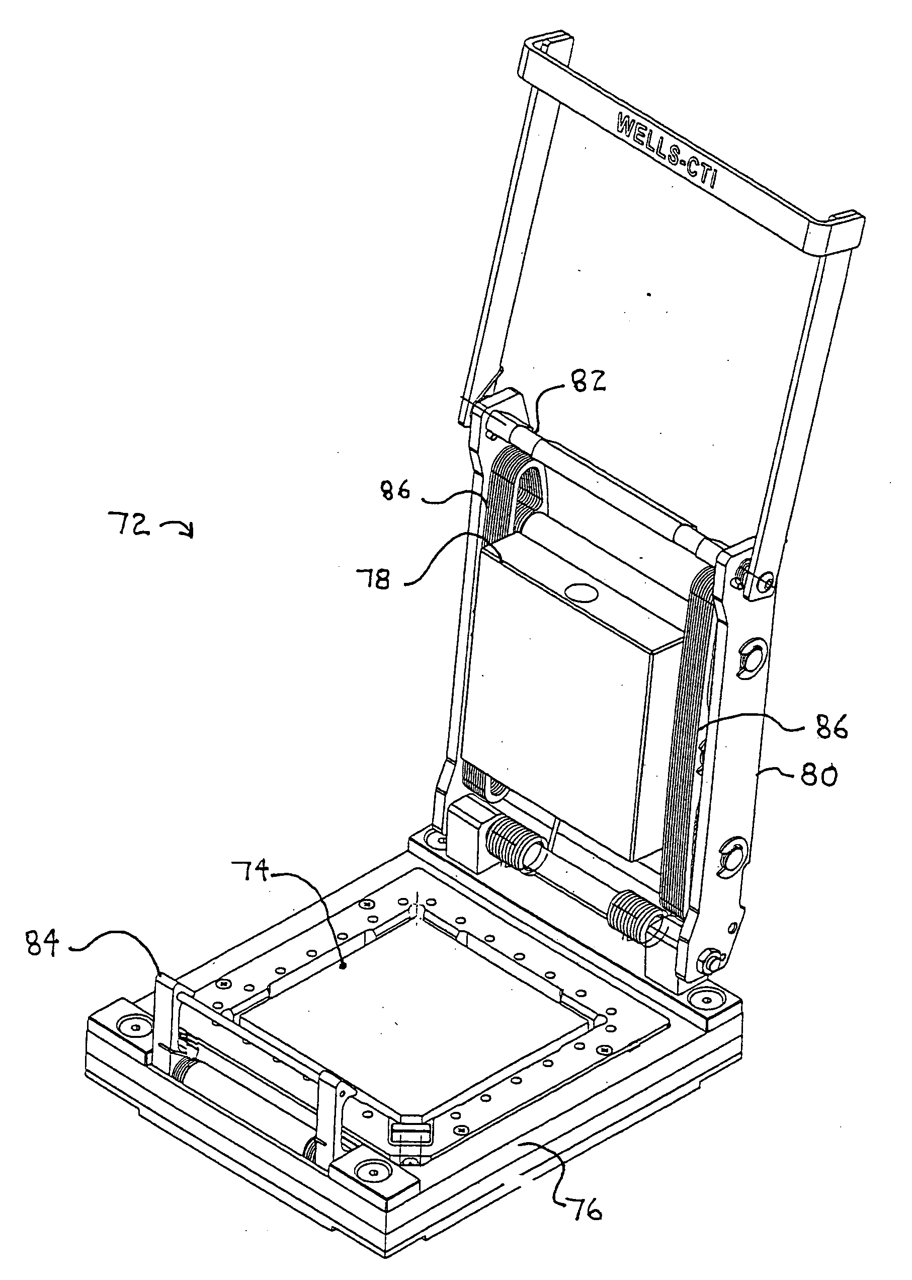
[0030]FIGS. 4 and 5 show an IC package testing device 72 according the invention in an open position. An IC package receiver 74 is contained within the base 76 of device 72 for receiving an IC package 88 (See FIGS. 7A-7C and 8A-8C) for testing such as burn-in testing. The pressure pad 78 is positioned within the lid assembly 80. When the device 72 is in a closed position, as shown in FIG. 5, the latch cam 82, positioned on lid 80, is engaged by the latch 84. A normal force is applied to the IC package 88 through the pressure pad 78 by the leaf springs 86. Referring to FIGS. 4 and 5, twenty leaf springs 86 are shown, with ten leaf springs stacked side-by-side on either side of the pressure pad 78 for a total of 20 leaf springs. It is preferable that at least two leaf springs 86 are used with at least one leaf spring positioned on either side of the pressure pad 78 to create a symmetrically balanced normal force in the pressure pad 78. A single such leaf spring 86 is shown in FIG. 9 a...


PUM


Abstract

An integrated circuit (IC) package testing device using a selectable number of leaf springs to provide a resilient and consistent normal force to the IC package and the method of operating the device. The leaf springs are shaped to provide the proper compliance and resilient force and are shaped to fit side-by-side within the lid of the device. The springs can be easily changed for differently sized IC packages.

Description

FIELD OF THE INVENTION [0001] This invention relates to integrated circuit testing sockets and more particularly to burn-in testing sockets. BACKGROUND OF THE INVENTION [0002] Integrated circuit (IC) packages must be tested after their manufacture, normally at elevated temperatures, which is the burn-in process. The integrated circuits are temporarily installed on a circuit board, tested, and then removed from the circuit board and shipped. Accordingly, test sockets are necessary to install the IC packages on the printed circuit board for testing. These test sockets include multiple contacts to connect each of the terminals of the IC package to corresponding conductors on the printed circuit board. Since the test sockets are used repeatedly in high volume IC package manufacture, it is desirable that the sockets be durable and capable of reliable, repeated operation. [0003] The test sockets are positioned on a burn-in board where the sockets are arranged in a relatively dense array t...

Claims


Application Information

Patent Timeline
IPC IPC(8): G01R1/04
CPCG01R1/0466
Inventor STUTZMAN, JAY
Owner WELLS CTI LLC
Why Eureka
Try Eureka