Logical operation circuit and logical operation device
a logical operation and circuit technology, applied in the direction of heating types, pulse techniques, instruments, etc., can solve the problem that the circuit cannot perform a logical operation on data
- Summary
- Abstract
- Description
- Claims
- Application Information
AI Technical Summary
Benefits of technology
Problems solved by technology
Method used
Image
Examples
Embodiment Construction
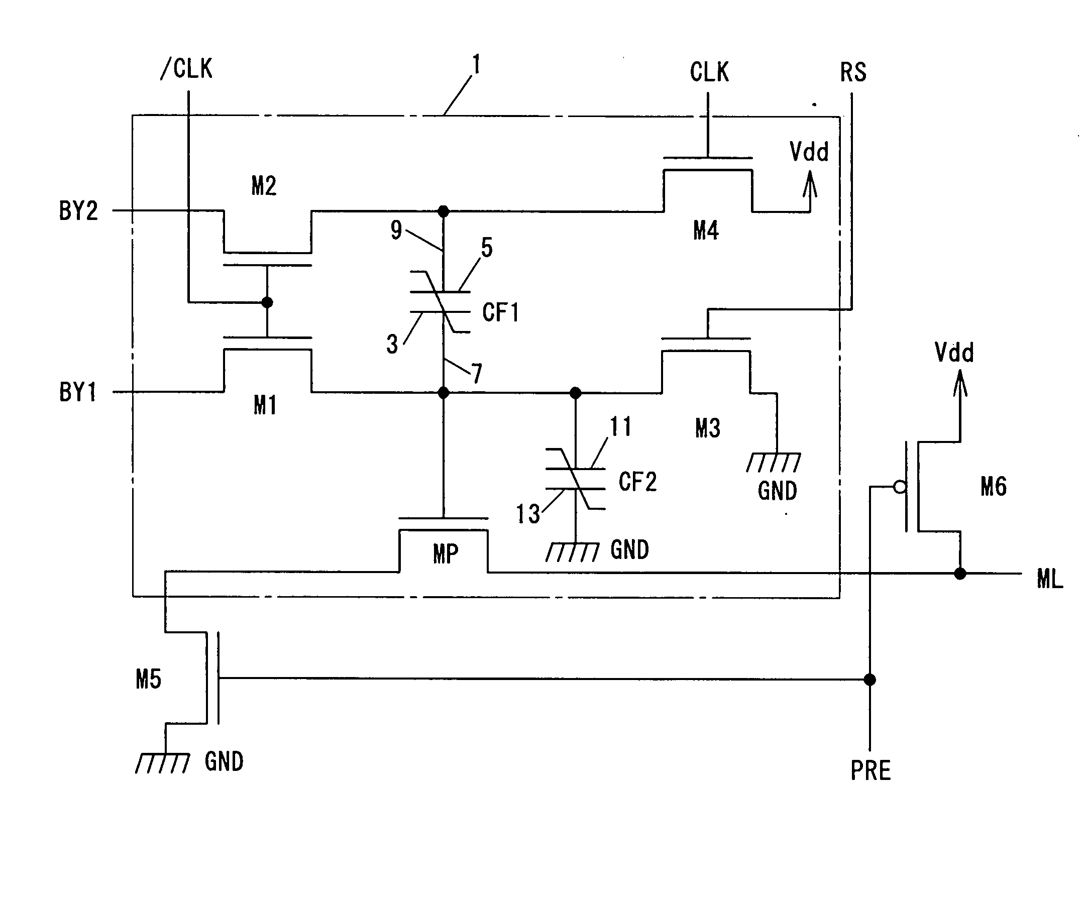
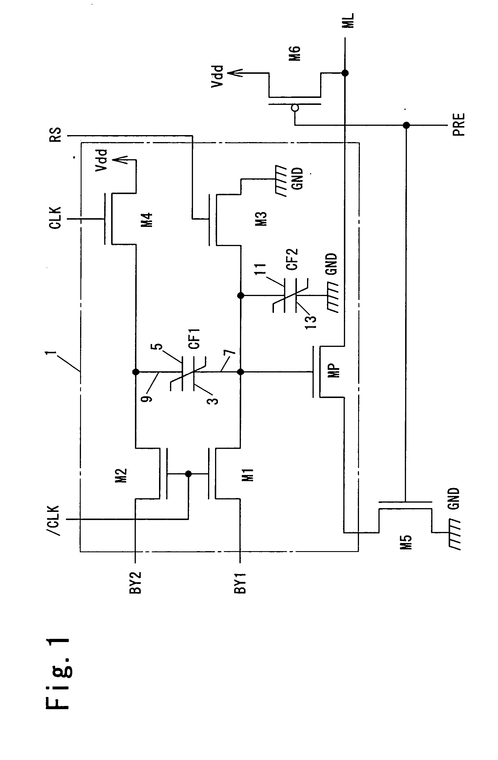
FIG. 1 is a circuit diagram illustrating a logical operation circuit 1 according to an embodiment of this invention. The logical operation circuit 1 has a first ferroelectric capacitor CF1 as a non-volatile memory element, a second ferroelectric capacitor CF2 as a load element, a transistor MP as an output transistor, and transistors M1, M2, M3 and M4. The second ferroelectric capacitor CF2 and the transistor MP constitute an operation result output section. The transistors MP, M1, M2, M3 and M4 are N-channel MOSFETs (metal oxide semiconductor field effect transistors).
The ferroelectric capacitor CF1 has a first terminal 3 connected to a first signal line 7 and a second terminal 5 connected to a second signal line 9. The first signal line 7 is connected to a gate terminal as a control terminal of the transistor MP.
The ferroelectric capacitor CF2 has a third terminal 11 connected to the first signal line 7 and a fourth terminal 13 connected to a ground potential GND as a first ref...
PUM
 Abstract
Description
Claims
Application Information
 - R&D
- Intellectual Property
- Life Sciences
- Materials
- Tech Scout
- Unparalleled Data Quality
- Higher Quality Content
- 60% Fewer Hallucinations
Browse by: Latest US Patents, China's latest patents, Technical Efficacy Thesaurus, Application Domain, Technology Topic, Popular Technical Reports.
© 2025 PatSnap. All rights reserved.Legal|Privacy policy|Modern Slavery Act Transparency Statement|Sitemap|About US| Contact US: help@patsnap.com


