Receiver optical sub-assembly with reduced back reflection

a technology of back reflection and optical sub-assembly, which is applied in the field of rosa with reduced back reflection, can solve the problems of back reflection being a source of optical noise, the level of back reflection, and the problem of back reflection still exist, so as to reduce any light coupling

Inactive Publication Date: 2005-01-27
JDS UNIPHASE CORP
View PDF13 Cites 30 Cited by
  • Summary
  • Abstract
  • Description
  • Claims
  • Application Information

AI Technical Summary

Benefits of technology

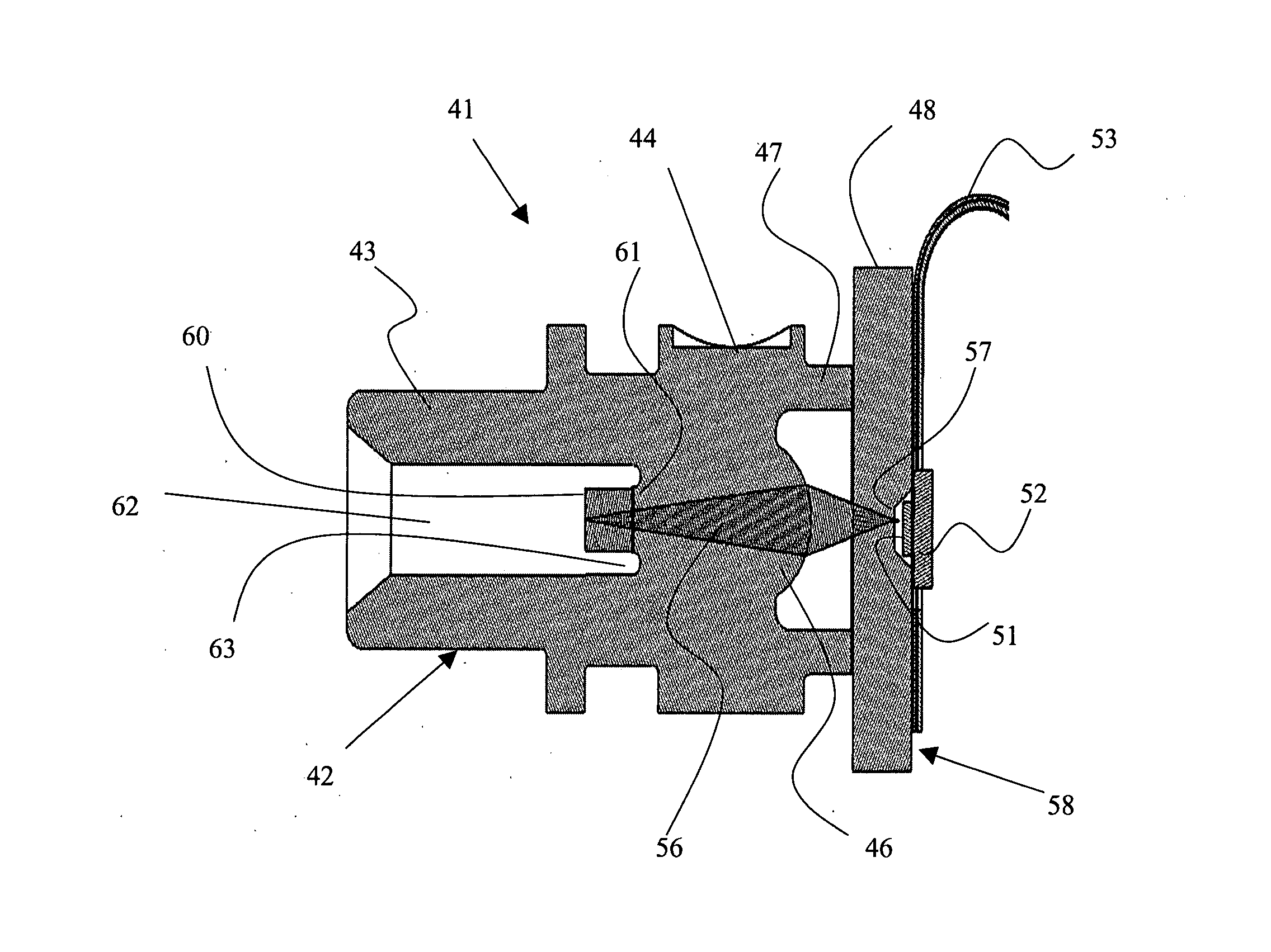
[0012] an optical insert coupled to the lens inside the optical coupler for contacting an end of the optical fiber when disposed therein, the optical insert having an index of refraction substantially the same as the optical fiber, whereby substantially no light is reflected at an interface of the optical insert and the optical fiber, and whereby any light reflected off an interface of the optical insert and the lens will have expanded by such an amount to greatly reduce any light coupling back into the optical fiber.

Problems solved by technology

Back reflection is a source of optical noise and the reduction of the level of back reflection is necessary for optimizing performance of the ROSA.
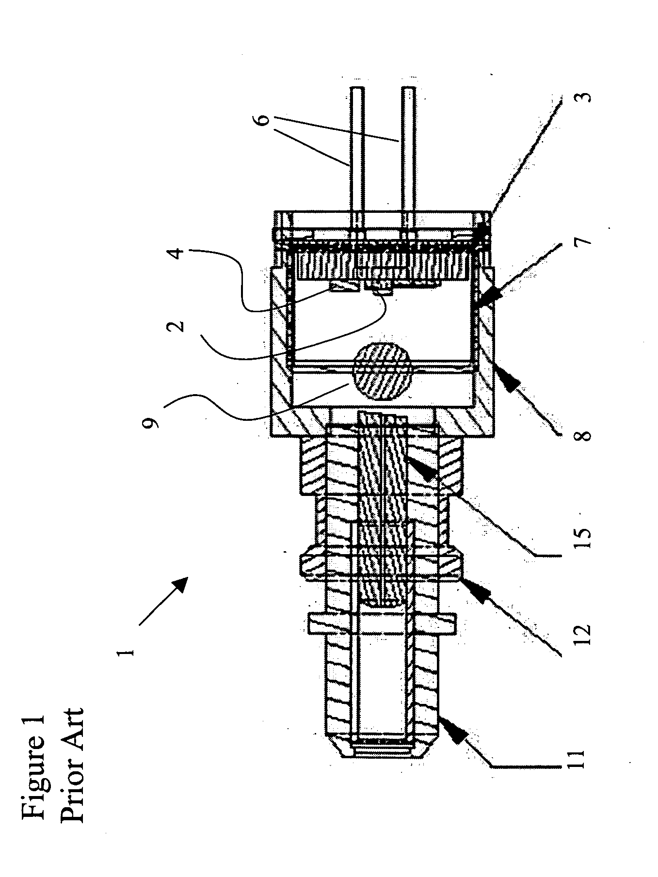
Unfortunately, the conventional structure of FIG. 1 includes several small requiring a complicated assembly process.
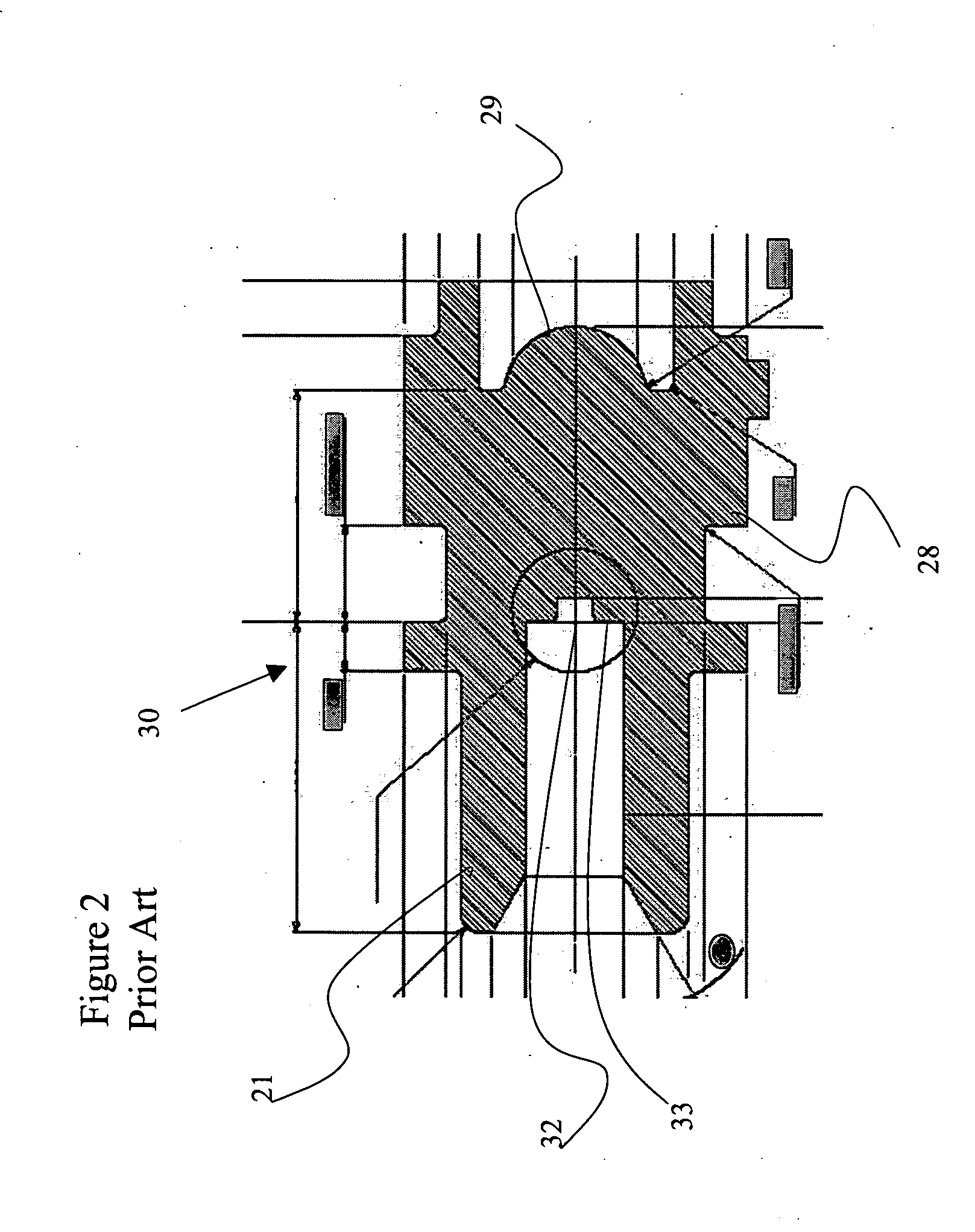
This ROSA design greatly simplifies the assembly process; however, the problem of back reflection still exists.

Method used


Image

  • Receiver optical sub-assembly with reduced back reflection
  • Receiver optical sub-assembly with reduced back reflection
  • Receiver optical sub-assembly with reduced back reflection

Examples


Embodiment Construction

[0019] With reference to FIG. 3, the ROSA assembly, generally indicated at 41, according to the present invention includes a molded plastic one-piece front-end unit 42 defining an optical connector 43, a housing 44, a focusing lens 46, and a mounting collar 47. The front-end unit 42 is constructed from an optical grade plastic, e.g. ULTEM1010. A substrate 48 is fixed to the mounting collar 47 for supporting a photo-detector 51 and other electronic devices, i.e. trans-impedance amplifier 52. Electrical leads, preferably in the form of flexible electrical cable 53, transmit electrical information to and from the photo-detector 51 and the other electronic devices, e.g. trans-impedance amplifier 52. The substrate 48 provides a stiffener for the flexible electrical cable 53. In a preferred embodiment, the substrate 48 is transparent to optical signal 56, thereby enabling the optical signal 56 to pass therethrough to the photo-detector 51. The photo-detector 51 is flip-chip mounted to the...


PUM


Abstract

The invention relates to a receiver optical sub-assembly (ROSA) for use in an optical transceiver to convert optical signals transmitted along an optical fiber into electrical signals for use by a host device. Conventionally, light exiting the optical fiber inside an optical coupler of the ROSA encounters a refractive index mismatched interface, e.g. fiber / air, causing a portion of the light to be reflected directly back into the fiber. To minimize back reflections at the interface with the optical fiber, an optical insert is provided having an index of refraction matching that of the optical fiber, thereby moving the mismatched interface remote from the end of the fiber to an interface of the optical insert and a lens, to which the optical insert is attached.

Description

CROSS-REFERENCE TO RELATED APPLICATIONS [0001] The present invention claims priority from U.S. Patent Application No. 60 / 489,440 filed Jul. 23, 2003, which is incorporated herein by reference.TECHNICAL FIELD [0002] The present invention relates to a receiver optical sub-assembly (ROSA), and in particular to a ROSA with reduced back reflection. BACKGROUND OF THE INVENTION [0003] Back reflection is a source of optical noise and the reduction of the level of back reflection is necessary for optimizing performance of the ROSA. Moreover, some communications standards, e.g. SONET, require that the receiver optical back reflection be less than specified limits, e.g. −27 dB. [0004] In a conventional ROSA 1, illustrated in FIG. 1, a photo-detector 2 is mounted on a substrate 3, along with other electronic circuitry, such as a trans-impedance amplifier 4. Electrical leads 6 extend outwardly from the rear of the ROSA 1 for electrically connecting the electronic circuitry to a transceiver circu...

Claims


Application Information

Patent Timeline
Patent Type & Authority Applications(United States)
IPC IPC(8): G02B6/24G02B6/42H04B10/06
CPCG02B6/4292G02B6/4207
Inventor MODAVIS, ROBERTGOODMAN, TIMOTHY DOUGLASLINDQUIST, ROGER T.HART, CHRISHOGAN, WILLIAM K.
Owner JDS UNIPHASE CORP
Why Eureka
Try Eureka