Cervical spine fixator and screwdriver used therefor

a technology for fixing screws and cervical spines, which is applied in the field of cervical spine fixators, can solve the problems of affecting the affected part, screw or other fasteners tending to loosen gradually after fixing, and jeopardizing the integrity of fixing, so as to reduce the feeling of foreign substances, reduce the thickness, and facilitate manufactur

Inactive Publication Date: 2005-01-27
U & I INC
View PDF12 Cites 78 Cited by
  • Summary
  • Abstract
  • Description
  • Claims
  • Application Information

AI Technical Summary

Benefits of technology

[0012] The present invention is disclosed to meet the above-mentioned requirements and it is an object of the present invention to provide a cervical spine f

Problems solved by technology

However, there is a drawback associated with this technique in that screws or other fasteners tend to gradually become loose after fixation.
Receiving a slight shock or vibration due to walking, climbing stairs or engaging in a vigorous activity following treatment increases this tendency, jeopardizing the integrity of the fixation.
Moreover, as the fasteners are loosened, the outward protrusion of the heads over other components of the fasteners can be a source of discomfort and potentially cause trauma to adjacent and surrounding soft tissue, resulting in a deformity of the affected part.
However, there is a drawback in the structure of fixing the auxiliary plate by the fastening member to thereby prevent the screws from backing out according to

Method used


Image

  • Cervical spine fixator and screwdriver used therefor
  • Cervical spine fixator and screwdriver used therefor
  • Cervical spine fixator and screwdriver used therefor

Examples


first embodiment

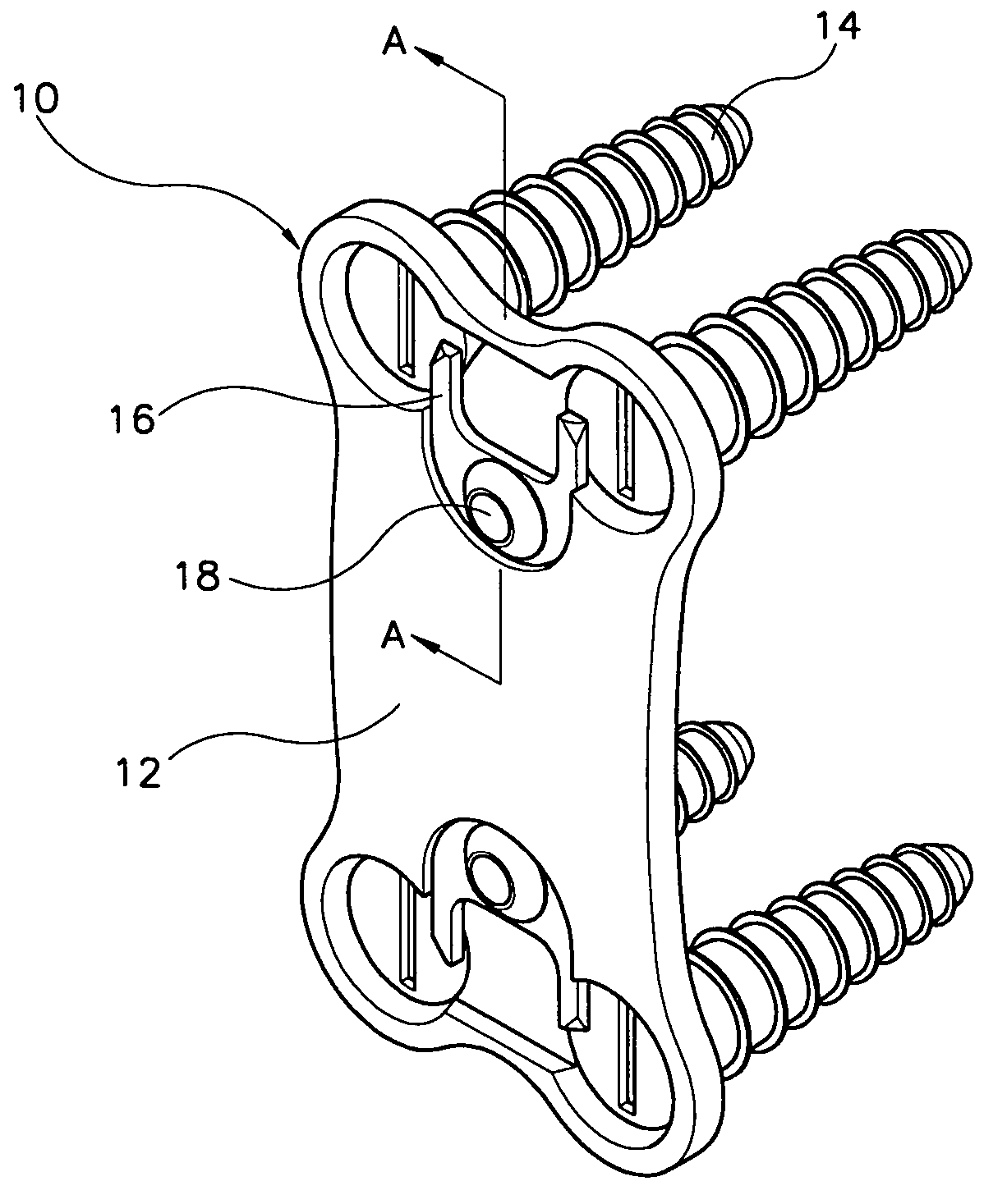
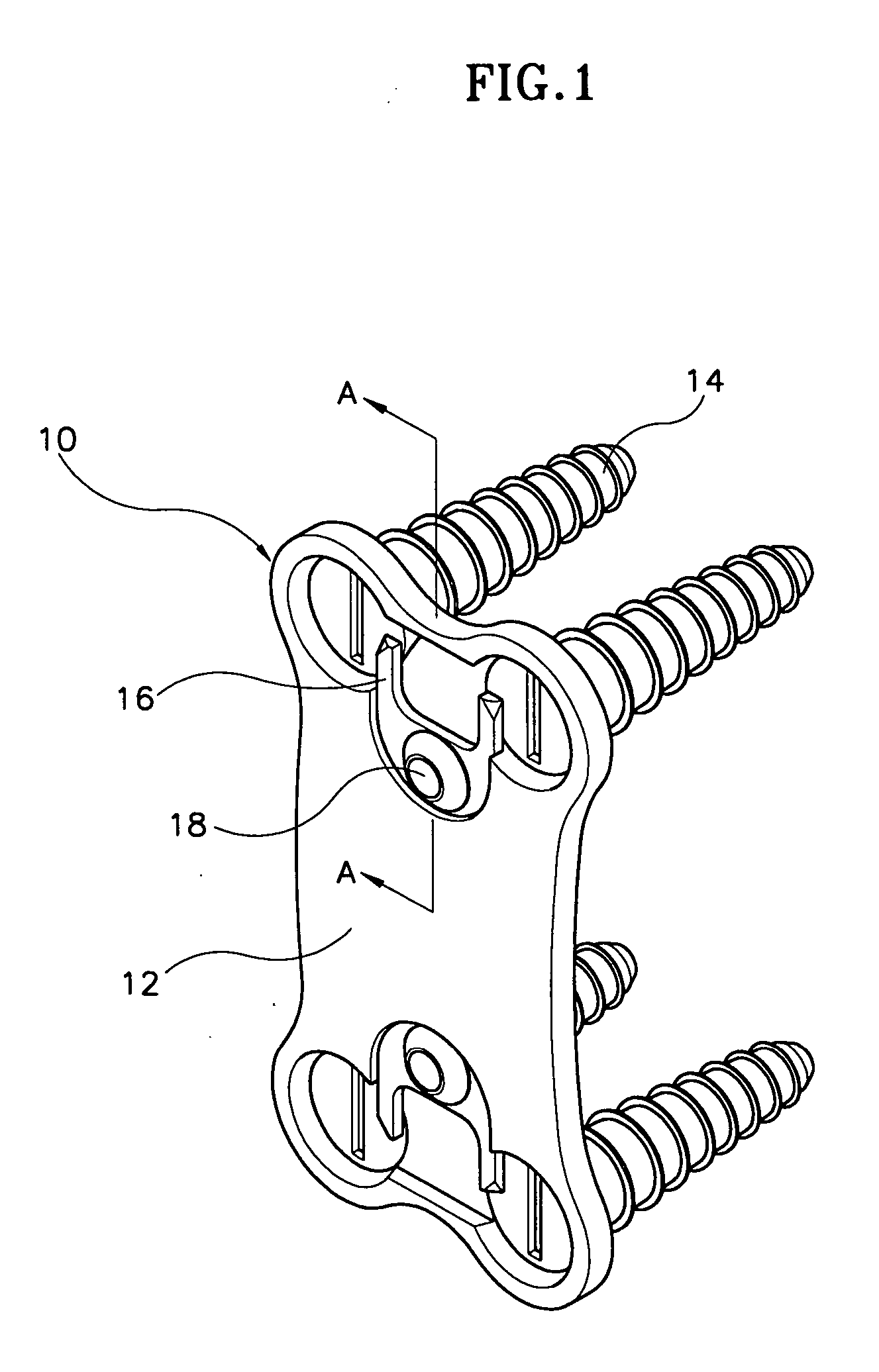
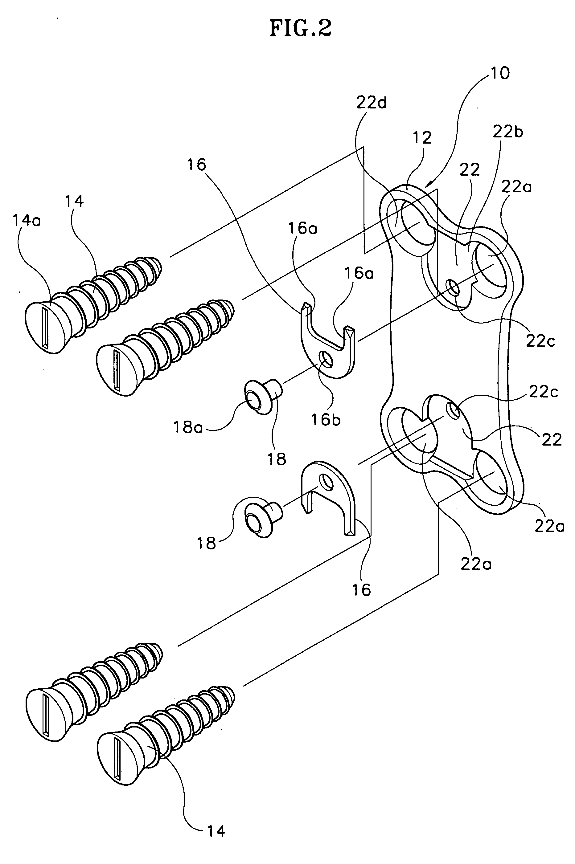
[0036] As shown in FIGS. 1 and 2, a cervical spine fixator (10) according to the present invention includes a plate (12) for being adjoined to a cervical spine fixture region, a plurality of screws coupled to the plate (12) and simultaneously fastened to the cervical spine, and a screw head fixture member (16) fixed to the plate (12) for preventing the screws from backing out.

[0037] The screw head fixture member (16) is fixed to the plate (12) by way of a well-known attachment method such as riveting (18) or welding. Generally, the plate (12) has a rectangular shape and is bent to conform to the curvature of the cervical spine. Receiving grooves are formed on the surface of the plate (12) opposite to the surface that is affixed to the cervical spine, for accommodating the head of the screw (14) and the screw head fixture member (16).

[0038] The receiving grooves (22) are formed at both ends of the plate (12), and each receiving groove (12) has an approximate T-shape when viewed from...

second embodiment

[0046]FIG. 6 is a perspective view for illustrating a cervical spine fixator according to the present invention.

[0047] The cervical spine fixator (110) according to the second embodiment of the present invention includes a screw head fixture member (116) of a U-shaped ring, and both ends (116a) of the U-shaped ring function as the protruders of the first embodiment. The rivet (118) of the present invention has a head large enough to press the curvature of the U-shaped ring. FIG. 7 is a cross-sectional view taken along an arrow of FIG. 6. Other constructions of the second embodiment are the same as those of the first embodiment such that further explanation will not be necessary.

third embodiment

[0048]FIGS. 8 and 9 are respectively a perspective view and an exploded perspective view of a cervical spine fixator according to the present invention, wherein the cervical spine fixator (210) includes a plate (212) for being attached to a cervical spine fixture region, a plurality of screws (214) coupled to the plate (212) and simultaneously fixedly inserted into the cervical spine, and a screw head fixture member (216) fixed to the plate (212) for preventing the screws (214) from being loosened. The screw head fixture member (216) is fixed to the plate (212) by way of a well-known coupling method such as riveting (218), welding or the like.

[0049] The plate (212) has a near rectangular shape and is bent to conform to the curvature of the cervical spine. The surface of the plate (212) opposite to the surface that is affixed to the cervical spine is formed with receiving grooves (222) for accommodating the screw head fixture member (216) and heads of the screws (214).

[0050] The rec...


PUM


Abstract

A cervical spine fixator and a screwdriver used therefore is disclosed wherein the fixator comprises plates (12, 212) for being adjoined to a cervical spine fixation region and a plurality of screws (14, 214). The plurality of screws are fixedly inserted into a patient's cervical spine and simultaneously coupled to the plates, wherein an adjacent region coupled with the screws in the plates is fixed with screw head fixture members (16, 216) having a protruder, which is deformed under the effect of pressure by a screw head when the screws are inserted and returns to their position of origin when the screw head is completely accommodated into the plates to be hitched by the screw head. The plates are formed thereon with receiving grooves (22, 222) for accommodating the screw head and the screw head fixture member. The receiving grooves are formed with openings into which the screws are inserted and a recess into which the screw head is received. The screw (214) formed with a groove of concaved curvature is installed or removed by a screwdriver (230) formed with a protruder of convex curvature, such that it is easy to manufacture, and the thickness of the plates is reduced, thus eliminating the feeling of a foreign substance after a surgical operation.

Description

FIELD OF THE INVENTION [0001] The present invention relates generally to a cervical spine fixator as an anterior cervical implant used for treating and correcting cervical disc diseases, cervical hernial disc diseases, cervical spondylosis myelopathy, cervical fractures, dislocations, tumors and cervical kyphotic deformity in orthopedics and neurosurgical fields. BACKGROUND OF THE INVENTION [0002] In general, cervical spine disorders are treated by holding respective cervical vertebrae in desired spatial relationships and orientations relative to each other. One common device for spinal fixation includes a plate and a fixation device comprising a plurality of screws for being fixedly inserted to the plate. [0003] The fixation device includes fixation screws for being driven or fastened into the upper and lower cervical vertebrae of the cervical spine, whereby respective vertebrae are fixed and treated by the locking force of the plates and the fixed screws. [0004] A surgical operati...

Claims


Application Information

Patent Timeline
IPC IPC(8): A61B17/58A61B17/70A61B17/80A61B17/86A61B17/88A61F2/44
CPCA61B17/7059A61B17/8875A61B17/8042A61B17/86
Inventor KOO, JA-KYO
Owner U & I INC
Why Eureka
Try Eureka