Method and system for enabling recovery of data stored in a computer network; a method and a system for recovering data stored in a computer network

Inactive Publication Date: 2005-01-27
AGENCY FOR SCI TECH & RES
View PDF19 Cites 23 Cited by
  • Summary
  • Abstract
  • Description
  • Claims
  • Application Information

AI Technical Summary

Benefits of technology

[0052] According to the preferred embodiment of the invention, the data recovery system further comprises at least an optical switch for switching a pair of optical fiber cables. The optical switch is used to provide an alternate path in the computer network in the event of a communication channel failure. For example, when one of the optical fiber is broken, the optical switch at a computer node before the broken portion can switch the flow of data to another fiber, thus avoidin

Problems solved by technology

One of the main problems of the persistence of data in the computer network is the loss of data due to connection or node failures or corruption of data by bit errors during data transmission.
Link or node failures can be caused by an operator pulling out a wrong connection of the computer network [2], failure of an amplifier, a backhoe cutting through a connection between the computer nodes, etc.
The loss or corruption of persistent data affects processes that are running on the distributed processors connected to the computer nodes which make use of the persistent data.
This results in roll-back actions to be performed to recover the lost or corrupted data.
In an example of a computer network having the computer nodes connected by optical fibers (fiber rings) wherein data is made to persist therein, a cut at any one of the optical fiber will result in loss of data circulating in that optical fiber.
In this case, conventional recovery techniques described in [4] and [5] which involves the use of an alternate communication path will not be sufficient as they do not recover data which is already lost.
However this alternative solutio

Method used


Image

  • Method and system for enabling recovery of data stored in a computer network; a method and a system for recovering data stored in a computer network
  • Method and system for enabling recovery of data stored in a computer network; a method and a system for recovering data stored in a computer network
  • Method and system for enabling recovery of data stored in a computer network; a method and a system for recovering data stored in a computer network

Examples


Embodiment Construction

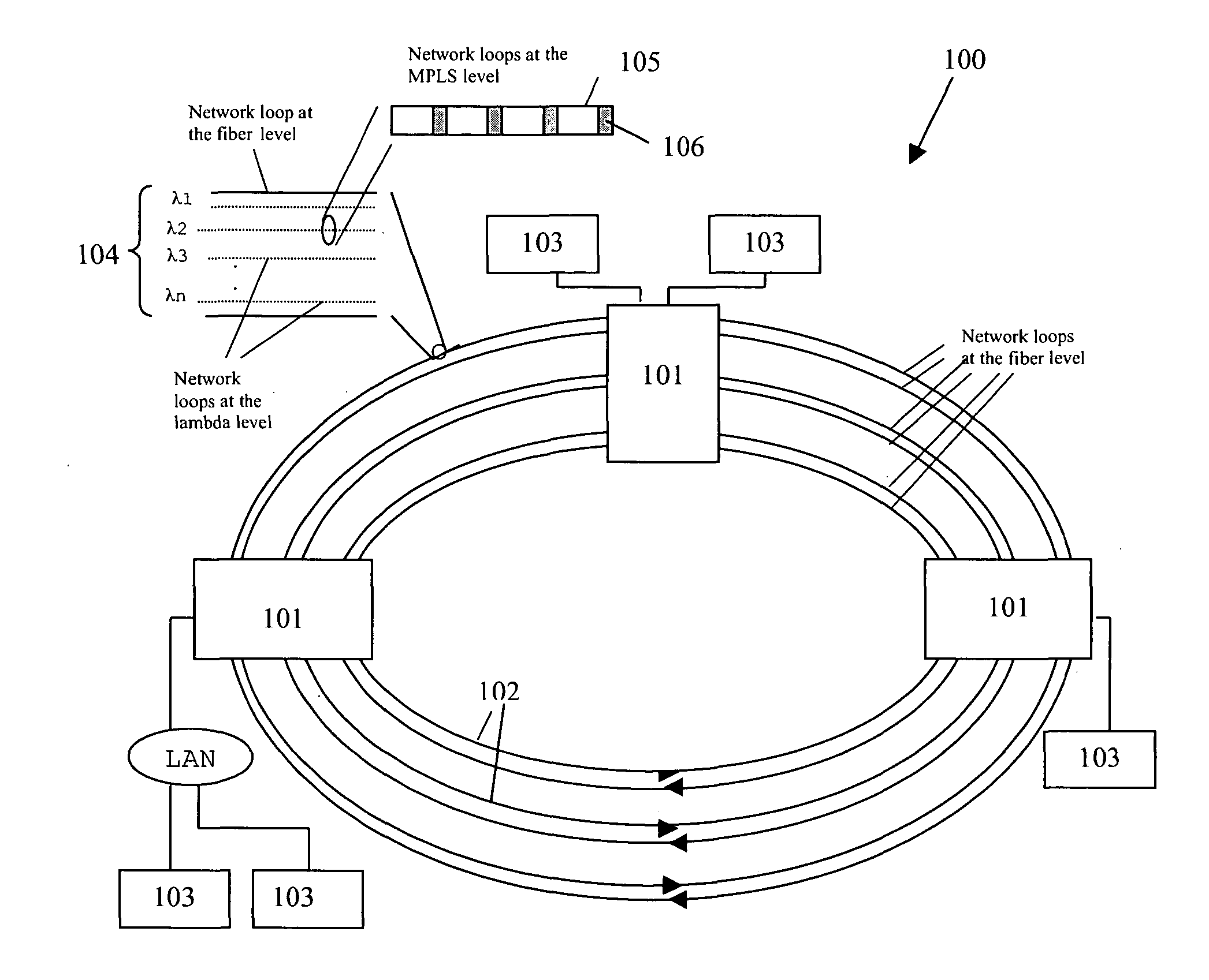
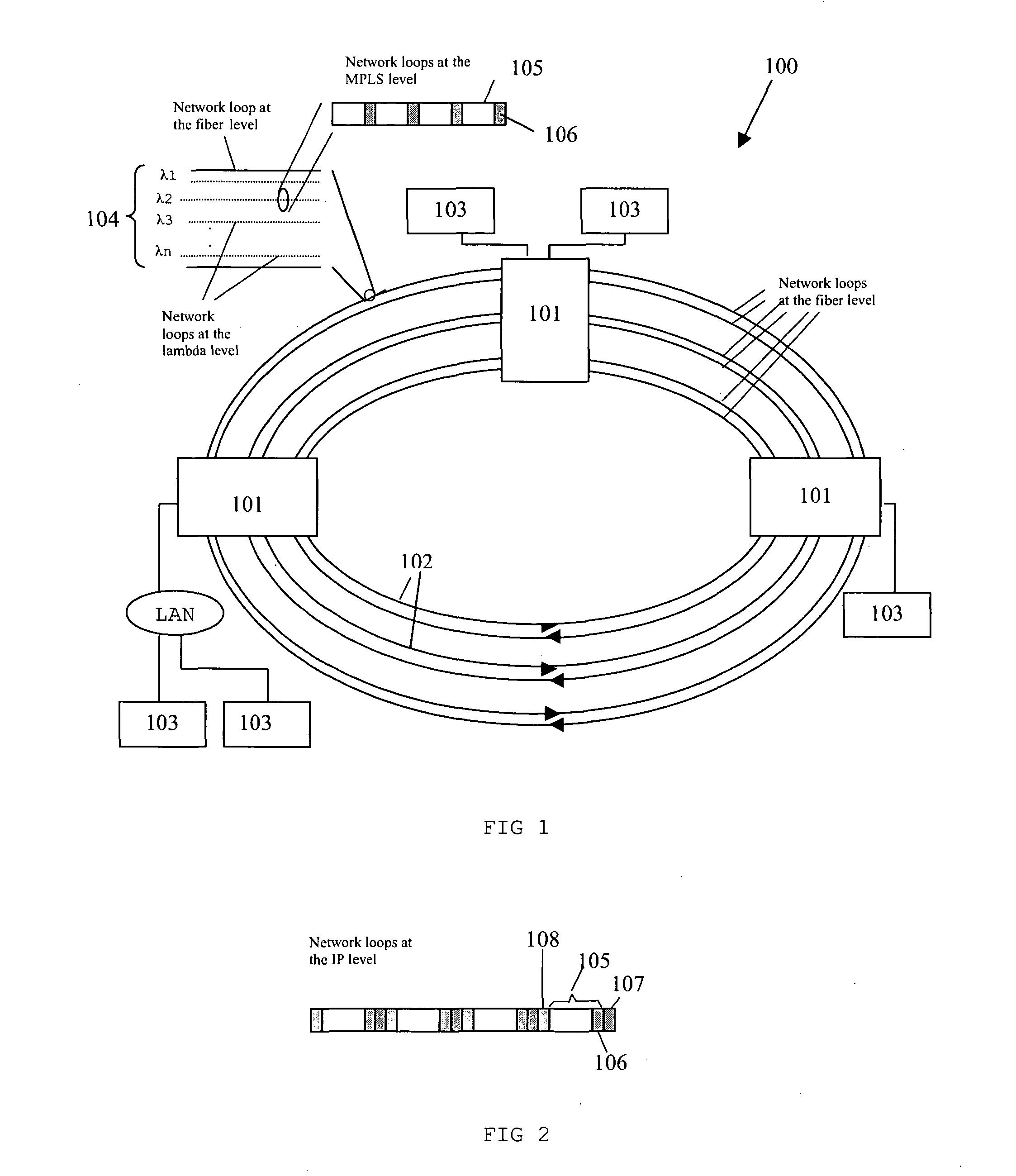
[0077]FIG. 1 shows a computer network 100 comprising a plurality of computer nodes 101 connected in a ring topology. The computer nodes 101 are connected to one another using optical fibers 102 in a form of a ring, and distributed processors 103 are connected to the computer nodes 101.

[0078] The Multiprotocol Label Switching (MPLS) is preferably used for controlling the forwarding of data packets in the computer network 100. This is because MPLS not only supports data packet switching at the computer nodes 101, but also supports lambda switching and fiber switching at the computer nodes 101, in the optical fiber network 100.

[0079] There are three levels of network loops in the optical fiber network 100: fiber level, lambda level and packet level. Network loop at fiber level refers to the optical fibers 102 which are used to connect each computer nodes 101. Network loop at lambda level refers to separate wavelengths, called lambdas 104, which are used as tracks in each optical fibe...


PUM


Abstract

A method for enabling recovery of data stored in a computer network, the computer network comprises a plurality of computer nodes, the method comprising the steps of generating a set of redundancy data based on a predetermined relationship between a first set of data and a second set of data, injecting the first set of data, the second set of data and the set of redundancy data into separate looping paths of the computer network, wherein a looping path is a path along a plurality of computer nodes in which data is transported, and the looping paths are defined in separate communication channels between the computer nodes and pass through at least one common node of the computer network, such that the redundancy data and the second set of data can be used to reconstruct the first set of data based on the predetermined relationship between the first and second set of data when the first set of data is lost, thereby enabling the recovery of data stored in the computer network.

Description

[0001] Data are normally stored in a computer network comprising computer nodes by storing the data at computer nodes or memory units connected to the computer nodes. In recent years, data is made to store in the computer network by looping the data in the network through a plurality of computer nodes along a defined looping path. [0002] Data stored in the computer network by looping therein is known as persistent data. Using the technique of data persistence in the computer network, wide-area storage devices like giant-sized disks or Inter-Processor Communication systems can be implemented more effectively. [0003] Inter-processor communication in a distributed computer environment using persistent data can be improved as data are now immediately available to any processors that are free to perform computations. Such an implementation can be seen in the Wavelength Disk Drive by CANARIE as disclosed in [1]. [0004] One of the main problems of the persistence of data in the computer ne...

Claims


Application Information

Patent Timeline
IPC IPC(8): G06F11/00H04L1/00
CPCG06F11/2007H04L1/0041H04L2001/0095H04L1/0072H04L1/0045
Inventor CHENG, HENG SENGNGOH, LEK HENGYUAN, ZHENG
Owner AGENCY FOR SCI TECH & RES
Why Eureka
Try Eureka