Cutting insert and milling cutter with such a cutting insert

Inactive Publication Date: 2005-02-03
KENNAMETAL INC
View PDF7 Cites 29 Cited by
  • Summary
  • Abstract
  • Description
  • Claims
  • Application Information

AI Technical Summary

Benefits of technology

In a further advantageous embodiment of the milling cutter, each plate seat provided for a cutting insert in the tool holder comprises, in addition to a support surface that is facing a corresponding base surface of the cutting insert and a contact surface that is facing a corresponding lateral surface of the cutting index, a take-up or receiving opening for take-up or receiving of an abutment pin that serves as axial abutment for the cutting insert. Since this abutment pin is not mounted until after the production of the plate seat, the support surface and the contact surface of the plate seat can be machined simultaneously in one operating step. This makes it possible that a precision of the planar extent of 10 μm can be achieved.
The advantages obtained with the invention reside primarily therei

Problems solved by technology

Of disadvantage are hereby the sensitivity with regard to angle errors during positioning of this linear cutting edge with respect to the work piece surface, such that a preferred approach that resides in use of only an end portion of the cutting edge at the surface that is to be machined is practically unavoidable and, accordingly, the posed requirement of an improved surface finish is practically not attainable.
Such a cutting edge that is circular or ellipsoidal in reference to the surface to be machined, however, due to values of curvature that are uniform or uniformly increasing commencing from the center of the cutting edge in the direction of the two cutting edge ends, entails undesirable small errors of toler

Method used


Image

  • Cutting insert and milling cutter with such a cutting insert
  • Cutting insert and milling cutter with such a cutting insert
  • Cutting insert and milling cutter with such a cutting insert

Examples


Embodiment Construction

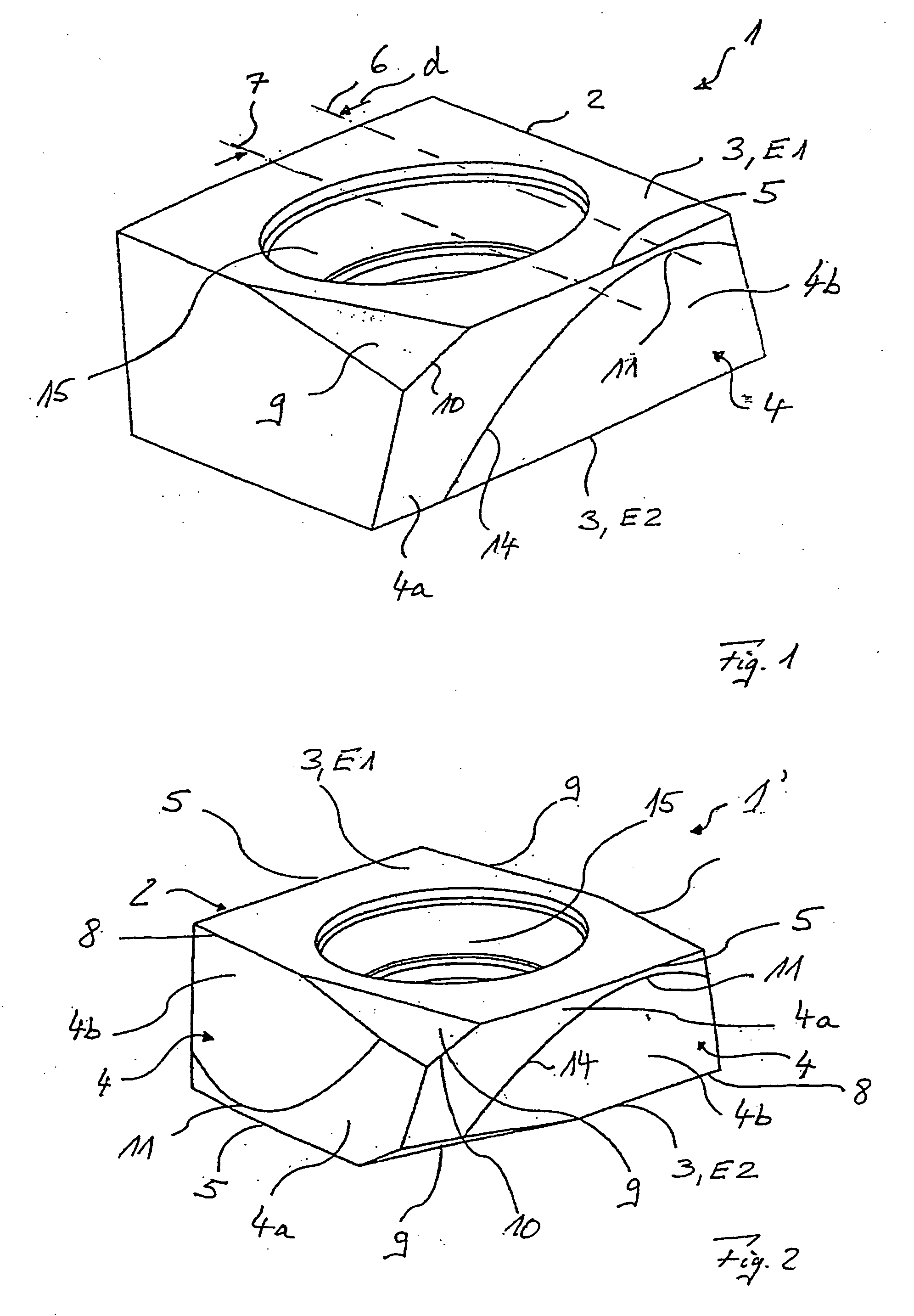
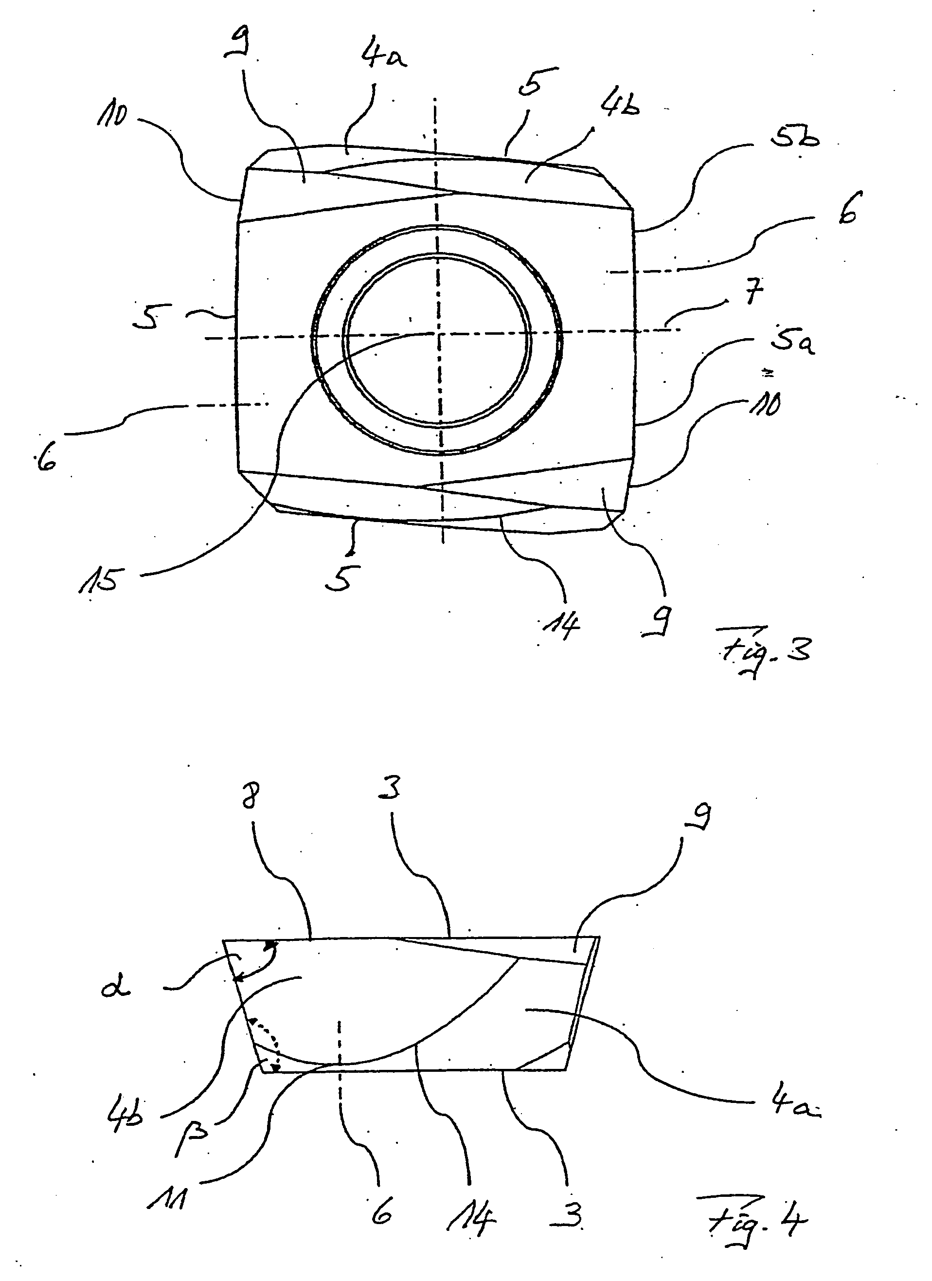
The cutting insert 1 illustrated in FIG. 1 comprises a base body 2 with two base surfaces 3 that are disposed in plate planes E1 and E2 that are disposed oppositely with respect to one another. The cutting insert 1 also comprises a lateral surface 4 with a cone-mantle-shaped surface portion 4a and a planar surface portion 4b. The cone-mantle-shaped surface portion 4a, as well as the base surface 3 that is facing it are disposed with respect to one another under an acute angle α (FIG. 4) and form a cutting edge 5. The planar surface portion 4b is disposed at an obtuse angle β (FIG. 4 with the oppositely disposed base surface 3.

The cutting edge 5 has a curved or arcuate course that is disposed within the plane E1 of the base surface 3, with off-centered—and, accordingly, asymmetrical—bulging of the cone-mantle-shaped surface portion 4a. Thereby, the cone axis 6 that is disposed in the plate plane E1 of the cone-mantle-shaped surface portion 4a, while forming the off-centered arcuat...


PUM


Abstract

A cutting insert 1, 1′, comprising opposite insert planes E1, E2 of a base 2 of one base area 3 wherein a conical surface section 4a of a lateral face 4 and the base area 3 facing the same form an acute angle alpha while forming a cutting edge 5, while a planar surface section 4b of the same lateral face 4 forms an obtuse angle beta with the opposite base area 3. The cone axis 6 of the conical surface area 4a lying in the insert plane E1, E2 runs off-set in parallel to the center insert axis 7 lying in the same insert plane E1, E2 while forming an off-center arcuate profile of the cutting edge 5. A milling cutter 17 comprising a number of such cutting inserts 1, 1′ is characterized in that a cutting insert 1, 1′ preferably disposed on the periphery of the center line M of a tool support 16 is off-set from the center line M by an angle phi equal to 5±3 degrees. The abstract of the disclosure is submitted herewith as required by 37 C.F.R. §1.72(b). As stated in 37 C.F.R. §1.72(b): A brief abstract of the technical disclosure in the specification must commence on a separate sheet, preferably following the claims, under the heading “Abstract of the Disclosure.” The purpose of the abstract is to enable the Patent and Trademark Office and the public generally to determine quickly from a cursory inspection the nature and gist of the technical disclosure. The abstract shall not be used for interpreting the scope of the claims. Therefore, any statements made relating to the abstract are not intended to limit the claims in any manner and should not be interpreted as limiting the claims in any manner.

Description

BACKGROUND 1. Technical Field This application relates to a cutting insert having opposite plate planes of a base body with respectively one base surface for each plane, as well as at least one lateral surface. This application relates furthermore to a milling cutter with such a cutting insert. The term cutting insert is particularly to mean an indexable cutting insert and the term milling cutter is particularly to mean a milling cutter for producing or machining finished surfaces. 2. Background Information Due to the increasing demands made of technical components or work pieces that are made by chip-forming machining, there arises particularly the demand for an improved quality of the surface finish. So as to meet this demand for smooth surfaces without furrows and grooves, and for finish-machining surfaces, particularly with a roughness (Rz) of less than 6 μm and a waviness (Wt) of less than 3 μm, there are also to be made special demands of the tools that are being used. Of ...

Claims


Application Information

Patent Timeline
IPC IPC(8): B23C5/20B23C5/22
CPCB23C5/207B23C5/2221B23C2200/0416B23C2200/085B23C2200/123B23C2200/125Y10T407/1924B23C2200/205B23C2200/367B23C2210/168B23C2250/16Y10T407/1964B23C2200/203B23C5/2213B23C5/202
Inventor SCHUFFENHAUER, MICHAELKRANZ, STEFFENBOGUTH, WERNER
Owner KENNAMETAL INC
Why Eureka
Try Eureka