Non-pressurized monotube shock absorber

a monotube shock absorber and non-pressurized technology, which is applied in the direction of shock absorbers, functional valve types, transportation and packaging, etc., can solve the problems of degrading the damping performance of the damper, the progressive and temperature dependent spring effect is usually unwanted in the suspension system, and the technology is believed to have significant limitations and shortcomings, so as to reduce the cost of manufacture and the service life of the damper of the present invention. , the effect of increasing the service li

Inactive Publication Date: 2005-02-03
LEIPHART TROY +1
View PDF9 Cites 46 Cited by
  • Summary
  • Abstract
  • Description
  • Claims
  • Application Information

AI Technical Summary

Benefits of technology

[0030] In these arrangements, there is no need for a floating piston and pressurized gas, because the base valve member provides the appropriate resistance to oil flow into the third chamber, so that cavitation is avoided in the rebound chamber during the damper's compression stroke. The base valve member also allows oil to be replenished into the compression cha

Problems solved by technology

This technology is believed to have significant limitations and shortcomings, including, but not limited to, that the shock absorbers or hydraulic dampers presently in use operate at elevated pressure that causes air to mix with the hydraulic fluid commonly used within these damper devices.
Th

Method used


Image

  • Non-pressurized monotube shock absorber
  • Non-pressurized monotube shock absorber
  • Non-pressurized monotube shock absorber

Examples


Embodiment Construction
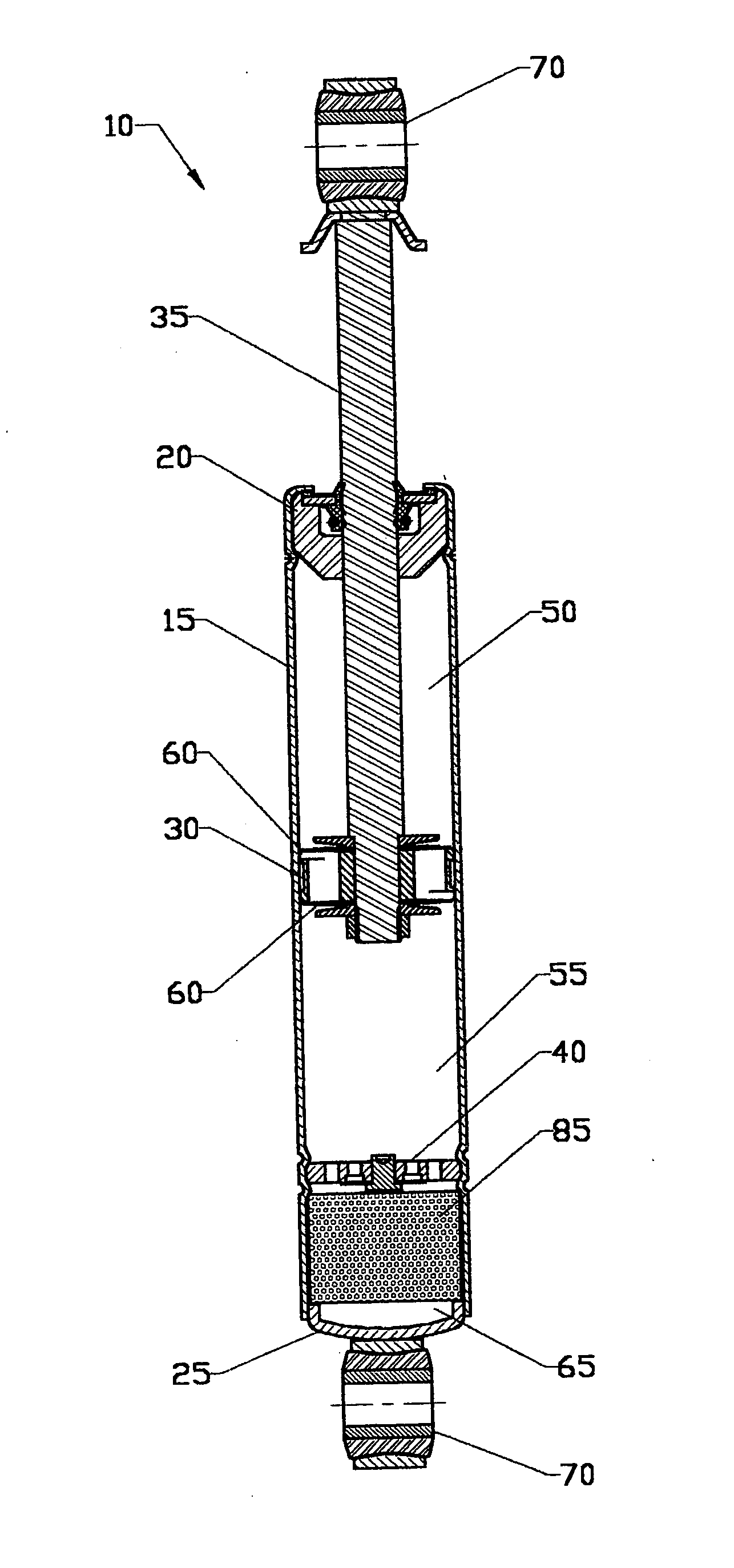
[0037] Nomenclature

[0038]10 Monotube Hydraulic Damper Device

[0039]15 Tube Body

[0040]20 Rod Guide Member

[0041]25 Base Member of Tube Body

[0042]30 Primary Piston Member

[0043]35 Rod Member

[0044]40 Base Valve Member

[0045]40a Deflective Disk Assembly

[0046]45 Compressible Bladder Member

[0047]50 Rebound Chamber of Tube Body

[0048]55 Compression Chamber of Tube Body

[0049]60 Valving of Primary Piston Member

[0050]65 Compensation Chamber of Tube Body

[0051]70 Mounting Members

[0052]75 Elastomeric Diaphragm Member

[0053]80 Fourth Chamber of Tube Body

[0054]85 Closed Cell Foam Bladder Member

[0055]90 Replenishing Valve Member

[0056]92 Flapper Portion of Replenishing Valve Member

[0057]100 Valve Plate Member

[0058]102 Metering Passages in Plate Member

[0059]104 Replenishing Passage in Plate Member

[0060]110 Metering Valve Member

[0061]112 Replenishing Passage in Metering Valve Member

[0062] Construction

[0063] The present invention is a non-pressurized monotube hydraulic damper device...


PUM


Abstract

A shock absorber of a monotube type utilizes a mechanically fixed base valve to regulate oil flow between the compression and compensation chambers, and a compressible bladder in the compensation chamber to allow volume compensation, which, together, eliminate the need for pressurized gas and a floating piston found in conventionally known monotube dampers.

Description

CROSS-REFERENCE TO RELATED APPLICATIONS, IF ANY [0001] This application claims the benefit under 35 U.S.C. §119 (e) of co-pending provisional application Ser. No. 60 / 491,303, filed 31 Jul. 2003. Application Ser. No. 60 / 491,303 is hereby incorporated by reference.STATEMENT REGARDING FEDERALLY SPONSORED RESEARCH OR DEVELOPMENT [0002] Not applicable. REFERENCE TO A MICROFICHE APPENDIX, IF ANY [0003] Not applicable. BACKGROUND OF THE INVENTION [0004] 1. Field of the Invention [0005] The present invention relates to shock absorbers (hydraulic dampers) for the suspension system of a motor vehicle or other mechanical device. In particular, the present invention relates to hydraulic dampers of the single or monotube type. [0006] 2. Background Information [0007] The state of the art includes various shock absorbers or hydraulic dampers used mainly for the suspension of a wide variety of motor vehicles. This technology is believed to have significant limitations and shortcomings, including, b...

Claims


Application Information

Patent Timeline
IPC IPC(8): B60G17/08F16F9/06F16F9/32F16F9/46
CPCB60G17/08F16F9/46F16F9/3235F16F9/061Y10T137/7891
Inventor LEIPHART, TROYHANSEN, JAMES D.
Owner LEIPHART TROY
Why Eureka
Try Eureka