Method for producing a component from fiber composite material

a composite material and component technology, applied in the direction of lamination, lamination apparatus, chemical apparatus and processes, etc., can solve the problems of not describing any reliable process production method for such components, complicated measures are required for health and safety and environmental protection, etc., and achieves high surface quality and dimensional stability.

Inactive Publication Date: 2005-02-03
DAIMLER AG
View PDF13 Cites 5 Cited by
  • Summary
  • Abstract
  • Description
  • Claims
  • Application Information

AI Technical Summary

Benefits of technology

[0023] In an optional intermediate step, the composite comprising fiber structure and core can be calibrated in a calibration mold after the impregnation of the resin and before the introduction into the conveyor oven. As a result, dimensional stability and a particularly high surface quality can be achieved.

Problems solved by technology

The solvent has to be removed again following the impregnation of the fiber structure, so that complicated measures are required for health and safety and environmental protection.
However, EP 1 109 657 B1 does not describe any reliable-process production method for such components which is suitable for mass production.

Method used


Image

  • Method for producing a component from fiber composite material
  • Method for producing a component from fiber composite material
  • Method for producing a component from fiber composite material

Examples


Embodiment Construction

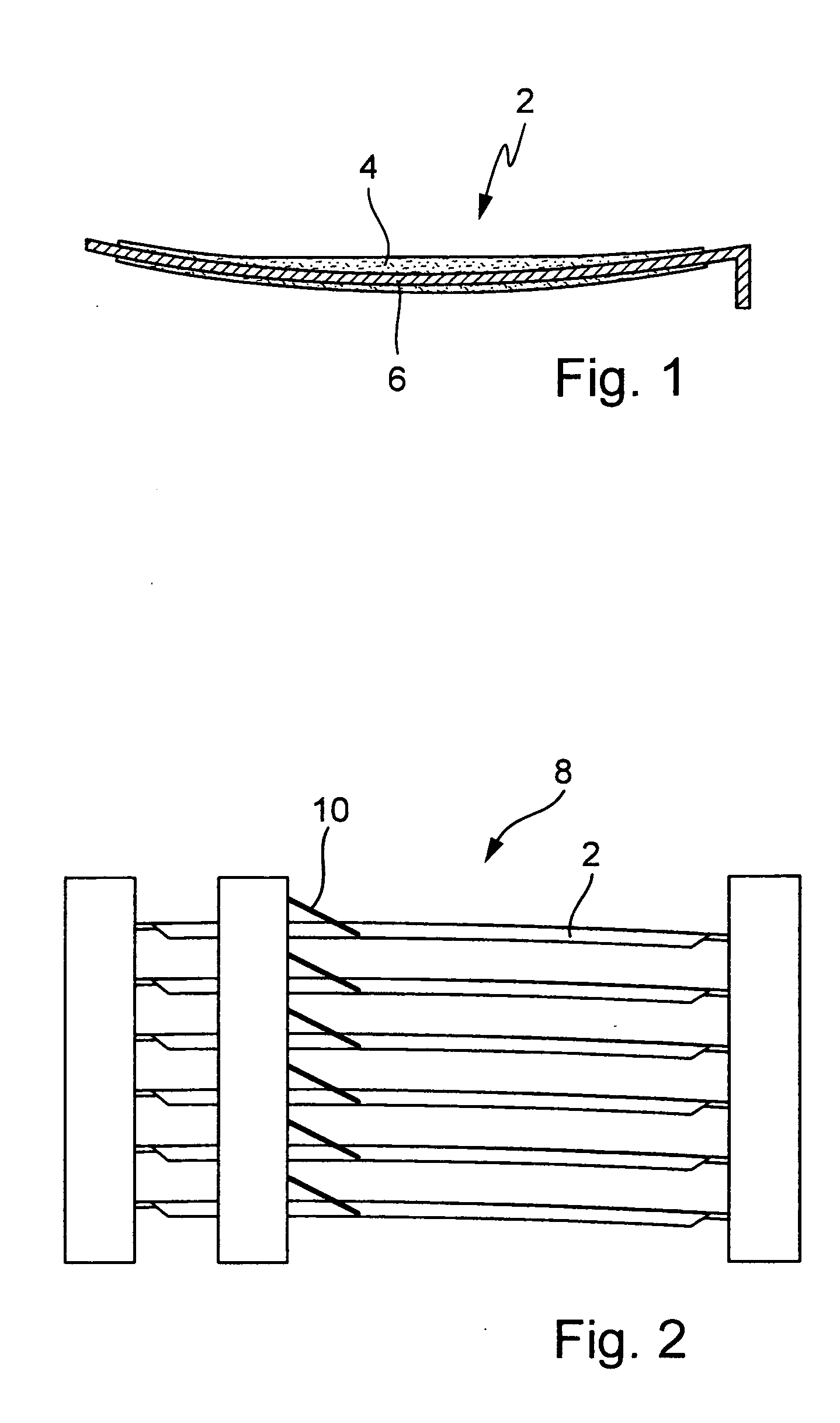
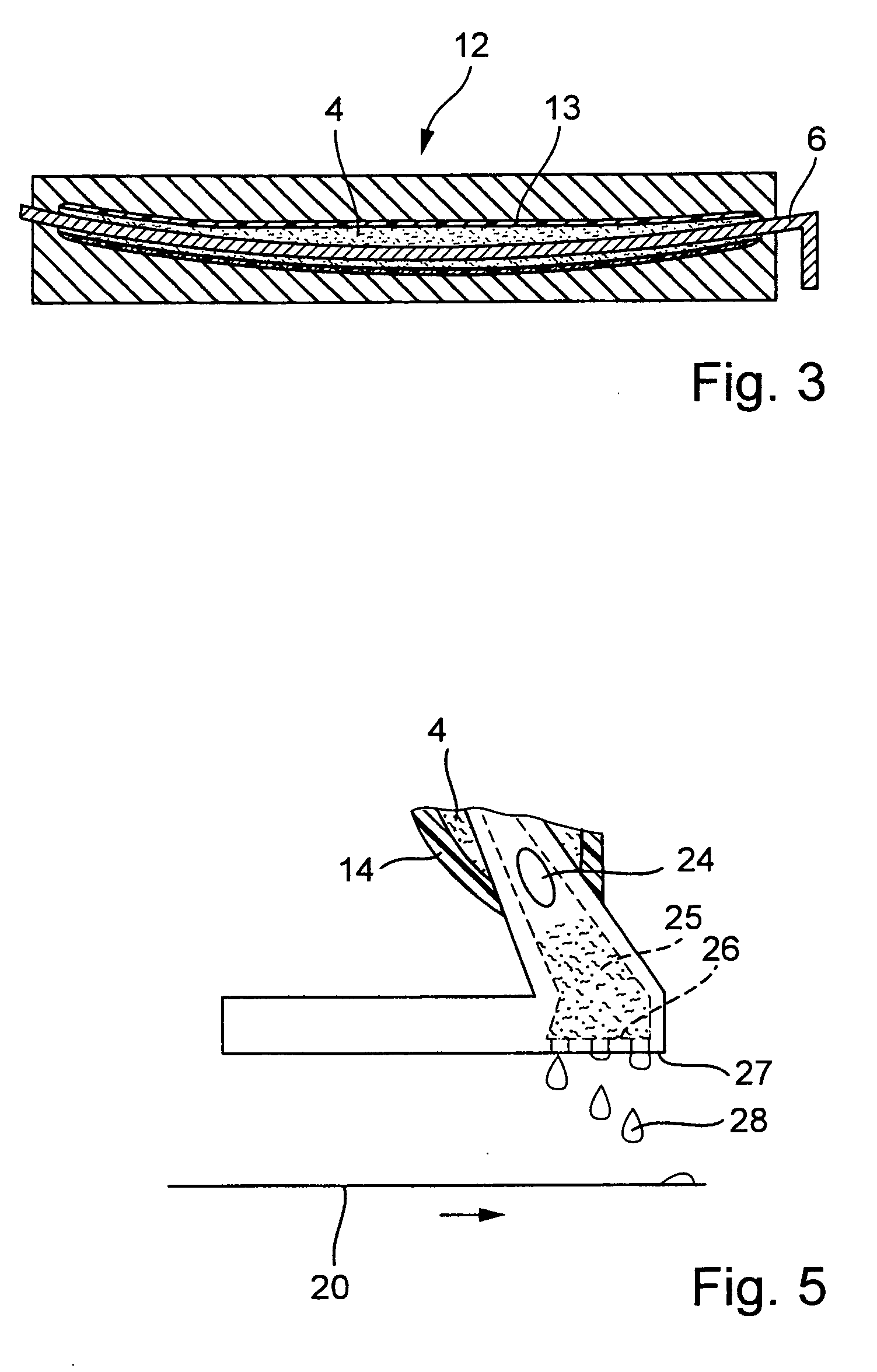
[0034] In FIG. 1, a core 2 which comprises a supporting core 6 and a core 4 of fusible material is illustrated. In order to produce the core 2, the supporting core 6 is inserted into an injection molding machine and encapsulated with a wax. The supporting core 6 can usually comprise a steel tube or an aluminum tube. It should be noted here that the supporting core 6 is of curved configuration. In the case of a solid core of metal, glass or plastic, such a shape could not be removed from a component 36 without destruction.

[0035] A core 2 of this type can be fitted to a suitable winding machine 8 together with a plurality of identical cores. A winding machine 8 is illustrated schematically in FIG. 2. In this case, a plurality of cores 2 are simultaneously provided with a reinforcing fiber 10. As an option, it may be expedient to provide the reinforcing fiber 10 with resin in a dip bath, not illustrated here. This leads to the fiber structure 14 already being impregnated with resin af...


PUM

PropertyMeasurementUnit
temperatureaaaaaaaaaa
passage timeaaaaaaaaaa

Abstract

The invention relates to a method for producing a partly hollow component (36) from a fiber composite material. In this case, a fusible core (4) is applied to a supporting core (6) by injection molding or casting. A reinforcing fiber (10) is then applied to the core (2). In the process, a fiber structure (14) is produced. The fiber structure (14) is impregnated with a resin. The fiber structure (14), together with the core (2), is put into a conveyor oven (18). During a continuous temperature process, first of all the resin is cured in order that the fiber structure (14) reaches a dimensionally stable state, and then the fusible core material is melted out of the core (2). The supporting core (6) is then removed from the component (36).

Description

BACKGROUND OF THE INVENTION [0001] 1. Field of Invention [0002] The invention relates to a method according to the features of claim 1. [0003] 2. Related Art of the Invention [0004] In the Japanese patent application JP 081 84 128 A, the production of a fiber reinforced structure component is described. In this case, this is a hollow chamber profile which is provided with a plurality of layers of fibers. It is possible to configure the hollow chamber profile with a plurality of subdivided cavities. However, JP 081 84 123 A leaves open the question of the extent to which such a hollow profile can be produced in a manner suitable for mass production. [0005] DE 197 36 573 A1 likewise describes a method for producing fiber composite materials. In this case, the matrix is represented by thermoplastic matrix plastics. Endless fibers are wound onto a core and impregnated with thermoplastic resins. According to DE 197 36 573 A1, the core onto which the endless fibers are wound is composed o...

Claims


Application Information

Patent Timeline
Patent Type & Authority Applications(United States)
IPC IPC(8): B29C45/26B29C33/52B29C45/14B29C70/06B29C70/16B29C70/42B29C70/54B29K91/00B29K105/08
CPCB29C33/52B29C70/54B29C70/42
Inventor KOSCHMIEDER, MARTIN
Owner DAIMLER AG
Why Eureka
Try Eureka